Method and device for continuously separating oil-water slag without dismantling and cleaning

A technology for separating oil and water without dismantling and washing, which is applied in chemical instruments and methods, multi-stage water/sewage treatment, flotation water/sewage treatment, etc. Slow speed and other issues, to achieve the effect of low processing cost, high processing efficiency and low cost

Inactive Publication Date: 2012-06-20
HUBEI UNIV +1
View PDF6 Cites 21 Cited by
  • Summary
  • Abstract
  • Description
  • Claims
  • Application Information

AI Technical Summary

Problems solved by technology

In short, the common disadvantages of the existing oil-water slag separation technology and devices are: the three-phase separation of oil-water slag cannot be well separated, the structure is complex, the processing efficiency is low, the processing speed is slow, and the processing cost is high. After the shutdown, the device shell is manually removed, and then the internal cleaning process is carried out

Method used


Image

  • Method and device for continuously separating oil-water slag without dismantling and cleaning
  • Method and device for continuously separating oil-water slag without dismantling and cleaning
  • Method and device for continuously separating oil-water slag without dismantling and cleaning

Examples


Embodiment 1

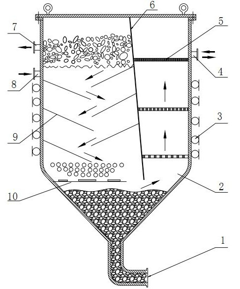
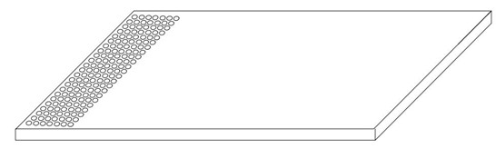
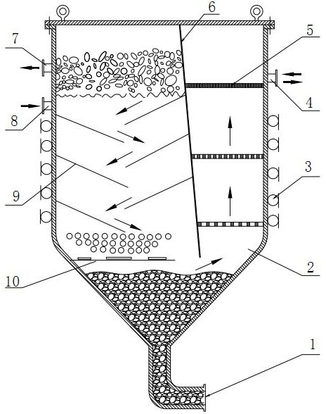
[0017] Embodiment one: as attached figure 1 The non-removable and washable continuous separation of oil and water slag shown in the device is a vertically placed vertical pot-shaped sealed container with a rectangular upper part and an inverted cone-shaped lower part. Ultrasonic generators 3 are evenly distributed on the four sides of the rectangular housing. Outside; the rectangular partition 6 divides the rectangular shell into two inner cavities with different volumes, the volume of the larger inner cavity is twice the volume of the smaller inner cavity; the lower end of the partition 6 is 5 degrees to the left; the oil discharge port 7. The waste water inlet 8 is located in the upper part of the larger inner cavity, and the six rectangular inclined plates 9 arranged alternately on the left and right sides are also located in the larger cavity. The inclined plates 9 (see attached figure 2 ) has a round hole at one end, and the round hole is located at the top of the slanti...

Embodiment 2

[0019] Embodiment 2: The waste water inlet 8 and the clean water outlet 4 are installed at the same level, but lower than the oil discharge port 7, and other parts of the structure are the same as in Embodiment 1.

[0020] The oil-water slag separation method of the non-removable and washable continuous oil-water slag separation device of the present invention is as follows:

[0021]After the waste water is pumped into the device from the waste water inlet, it hits the central partition 6 and the upper inclined plate 9, and then flows downward, most of the oil layer floats on the upper part, and the coarse slag sinks. After the water flows through the second and third layers of sloping plates 9 and turns back and forth, the coarse slag basically gathers on the top of the sloping plates 9, and after gathering to a certain amount, it automatically falls into the bottom of the device tank bottom tank 2 from the bottom end. The fine oil droplets are separated and enriched to the l...


PUM

PropertyMeasurementUnit
porosityaaaaaaaaaa

Abstract

The invention provides a method and a device for continuously separating oil-water slag with dismantling and cleaning. Due to the adoption of a technology of combining gravity separation, air floatation separation, ultrasonic separation and cleaning and the like, wastewater containing oil and slag is separated and treated. The device is a vertical tank type sealing container which is arranged vertically, wherein the upper part of the container is rectangular; the lower part of the container is of an inverted pyramidal shape; a rectangular casing is externally surrounded by an ultrasonic generator and is internally divided into two inner cavities with the different sizes by a partition board; an oil drain port, a wastewater inlet, rectangular inclined plates arranged in a staggered way andan air floatation coiled pipe are arranged in the bigger inner cavity; a clear water outlet, a rectangular dense hole filtering mesh plate, a rectangular mesoporous filtering mesh plate and a rectangular gross porous filtering mesh plate are respectively arranged in the smaller inner cavity; and a slag discharging opening is connected to the lower end of a groove body at the tank bottom of the inverted pyramidal shape. The device is advanced in separation method, simple in structure and high in treatment efficiency; and particularly, in the production, internal cleaning can be carried out without stopping work and dismantling a casing of the device, and thus the continuous high-efficiency operation of the equipment can be ensured.

Description

technical field [0001] The present invention relates to a method and device for continuous separation of oil and water slag without dismantling and cleaning, in particular to a continuous and dynamic separation equipment for the treatment of oily and slag-containing wastewater or other liquids containing oil and slag, which belongs to the separation and filtration equipment in fluid machinery technology field. Background technique [0002] In metallurgical and coking industries, oil fields, hospitals, hotels, restaurants and pharmaceuticals, fine chemicals, petrochemical processing and other industries, the treatment of oily and slag-containing wastewater, or the separation technology and equipment of other oily and slag-containing liquids are related to waste treatment and utilization. It is an important content that is conducive to environmental protection. The existing oil-water residue separation methods mainly include: gravity separation technology and centrifugal s...

Claims


Application Information

Patent Timeline
Patent Type & Authority Applications(China)
IPC IPC(8): C02F9/08C02F1/36C02F1/24
Inventor 王海人曹志勇王麒钧屈均娥周洋张俊
Owner HUBEI UNIV
Why Eureka
Try Eureka