Rotary electroplating device

A technology of rotating electroplating and electroplating tanks, applied in electrolytic components, electrolytic processes, etc., can solve problems such as the uniform thickness of the coating layer, achieve good electroplating effects, facilitate observation, and increase reliability

Active Publication Date: 2012-06-20
HENGLI ELETEK
View PDF8 Cites 19 Cited by
  • Summary
  • Abstract
  • Description
  • Claims
  • Application Information

AI Technical Summary

Problems solved by technology

However, for some complex shapes or some shell parts, this level of revolution and rotation still cannot solve the proble

Method used


Image

  • Rotary electroplating device
  • Rotary electroplating device
  • Rotary electroplating device

Examples


Embodiment Construction

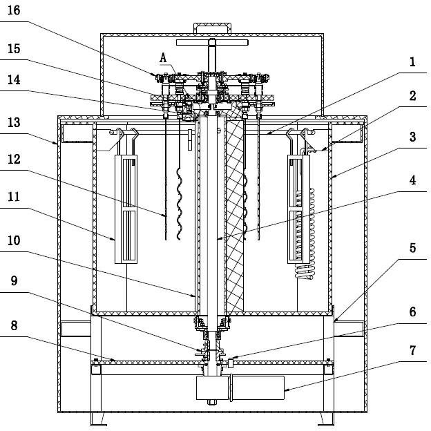
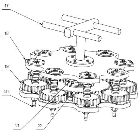
[0025] like figure 1 As shown, the rotary electroplating device of the present invention includes an electroplating tank 3, a driving mechanism positioned on the electroplating tank support 5, a rotating disk system 16 connected to the driving mechanism and a conductive system for electroplating operations; wherein, electroplating The inner wall of the upper end of the groove 3 is provided with a support plate 2 for fixing the annular titanium-clad copper anode conductive ring 1, and the annular titanium-clad copper anode conductive ring 1 is provided with an anode titanium blue 11; the driving mechanism includes a motor reducer 7 , a shaft coupling 9 and a central rotating shaft 4, the periphery of the central rotating shaft 4 is provided with a cylinder 10, the coupling 9 is connected with the lower end of the central rotating shaft 4 through a motor output shaft, and the central rotating shaft 4 The upper end protrudes upwards from the electroplating tank 3 and is connected...


PUM


Abstract

The invention discloses a rotary electroplating device, comprising an electroplating groove, a driving mechanism located on an electroplating groove bracket and a conductive system for electroplating. The driving mechanism comprises a motor reducer, a shaft coupler and a center rotating shaft. The shaft coupler is connected with the lower end of the center rotating shaft; and the upper end of the center rotating shaft upwards stretches out the electroplating groove and is connected with a rotary disc system capable of rotating along with the center rotating shaft. The rotary disc system comprises a rotary flange disc with a system center shaft, and a gear mechanism which can be driven by the center rotating shaft to rotate and is connected on the rotary flange disc. According to the rotary electroplating device disclosed by the invention, not only the revolution of a working piece around the center rotating shaft but also the autorotation of the working piece exist in the solution by a planet gear mechanism. Therefore, the uniformity of a plating layer of the working piece is further improved in a manner of combining the revolution with the autorotation. The electroplating effect is good for the complex working pieces, particularly shell parts, and the uniform plating layer can be obtained simultaneously.

Description

[0001] technical field [0002] The invention relates to a rotary electroplating device, which belongs to the field of electroplating industrial equipment. [0003] Background technique [0004] Generally, electroplating equipment drives the plated parts to move up and down in the plating tank to obtain a relatively uniform coating; or drives the workpiece to revolve to obtain a relatively uniform coating. Spin electroplating is a kind of electroplating method in which the workpiece (cathode) to be plated is continuously rotated relative to the anode during the electroplating process, and electroplating is realized during rotation. The workpiece electroplated by rotary electroplating has the advantages of uniform coating and good quality. The spin-down electroplating device with application number 200910234313.2 includes: an electroplating tank, the tank bracket is located below the tank; a supporting rotating mechanism, including a metal rotating shaft (with an insulating ...

Claims


Application Information

Patent Timeline
IPC IPC(8): C25D17/00C25D5/00
Inventor 沈剑陶善保季宏飞
Owner HENGLI ELETEK
Why Eureka
Try Eureka