Flexible energy-consumption frame filling wall

A technology for infilling walls and frames, applied in the directions of walls, building components, and anti-seismic, can solve the problems of sudden stiffness, shear failure of short columns, and increased horizontal seismic force, so as to achieve fast and convenient installation, reduce seismic response, and reduce manufacturing costs. low effect

Inactive Publication Date: 2012-06-20
NANJING UNIV OF TECH
View PDF6 Cites 21 Cited by
  • Summary
  • Abstract
  • Description
  • Claims
  • Application Information

AI Technical Summary

Problems solved by technology

The existence of infill walls improves the overall ability of the structure to resist lateral loads, but it also creates corresponding problems. First, the difference in the number and arrangement of infill walls in different structural layers forms the discontinuity of the upper and lower infill walls. The sudden change of stiffness between adjacent floors causes the weak layer to be damaged or collapsed; second: the lateral restraint of the frame column by the infill wall with openings or windows reduces the actual shear-span ratio of the frame column and causes short column shear third: the addition of filling walls increases the overall rigidity of the entire frame structure system, and the horizontal seismic force on the structure will also increase; fourth: the uneven layout of filling walls causes structural torsional damage

Method used


Image

  • Flexible energy-consumption frame filling wall
  • Flexible energy-consumption frame filling wall
  • Flexible energy-consumption frame filling wall

Examples


Embodiment Construction

[0027] The present invention will be further described below in conjunction with the accompanying drawings and embodiments.

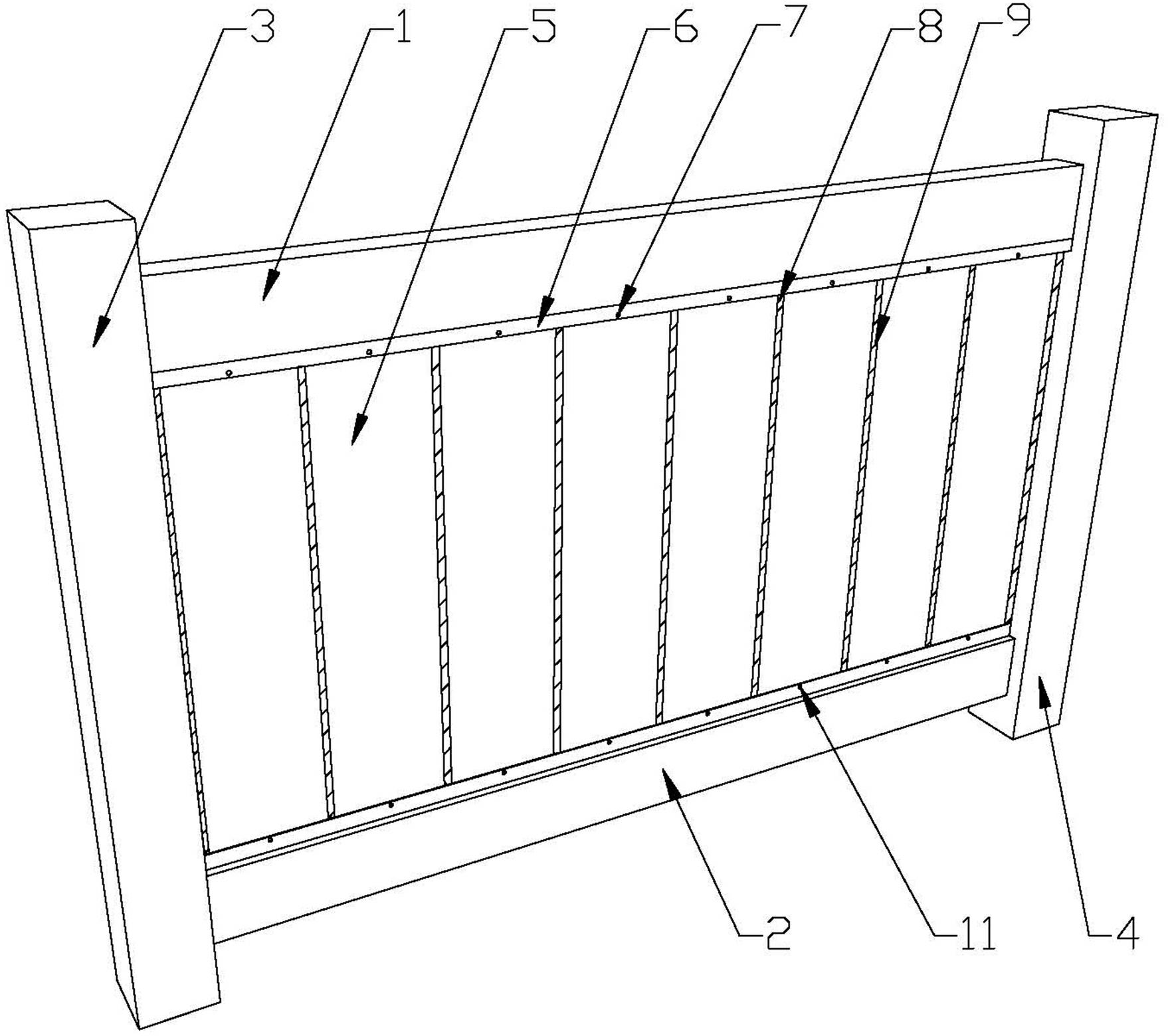
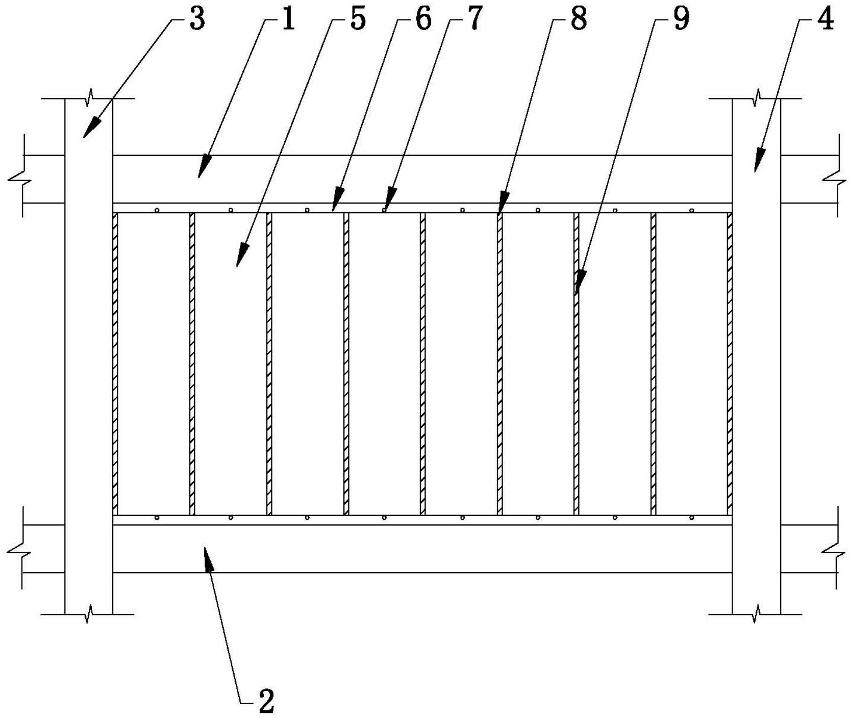
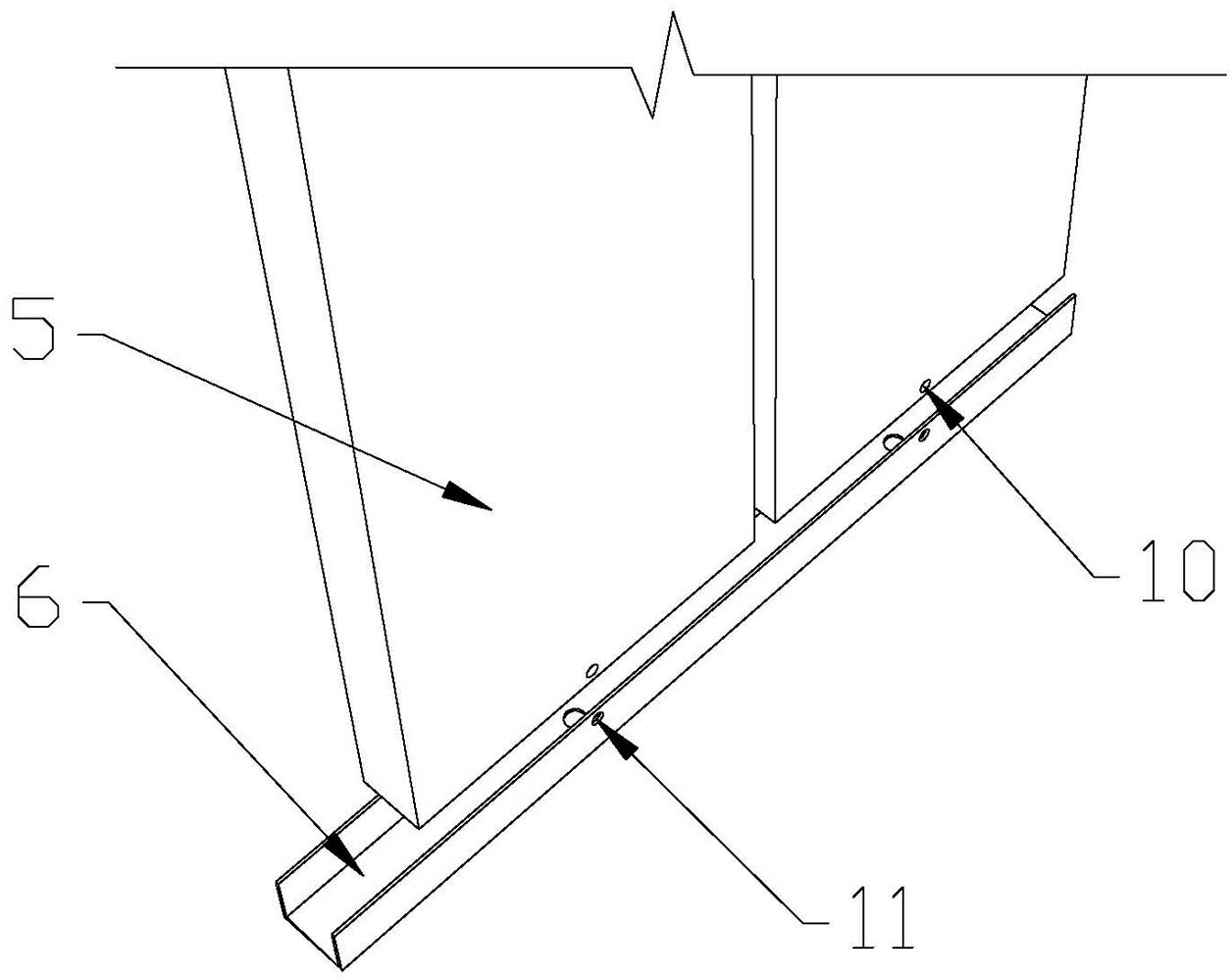
[0028] Such as Figure 1-5 Shown: a flexible energy-dissipating frame filled wall, including the upper frame beam 1, the lower frame beam 2, the left frame column 3 and the right frame column 4 and the partition wall strip 5, the upper frame beam 1, the lower frame beam The frame beam 2, the left frame column 3 and the right frame column 4 are concrete frames or steel frames, and the partition wall strips 5 include autoclaved aerated concrete strips, industrial ash concrete porous strips, and glass fiber reinforced cement lightweight porous strips board, gypsum slats, plant fiber slats, fly ash foam cement slats and silicon magnesium aerated cement slats. In the lower side of the beam bottom of the upper frame beam 1 and the upper side of the beam top of the lower frame beam 2 opposite to it, there are respectively fixed U-shaped steel plate grooves 6 ...


PUM

PropertyMeasurementUnit
Apertureaaaaaaaaaa

Abstract

The invention discloses a flexible energy-consumption frame filling wall, comprising an upper frame beam (1), a lower frame beam (2), a left frame column (3), a right frame column (4) and partition wall strip plates (5) which form a frame structure. A U-shaped steel plate groove (6) with a downward opening and a U-shaped steel plate groove (6) with an upward opening are respectively fixedly arranged on the beam bottom lower side of the upper frame beam(1) and the beam top upper side of the lower frame beam (2) opposite to the upper frame beam (1), the partition wall strip plates (5) are vertically arranged in the U-shaped steel plate grooves (6) and are connected with the U-shaped steel plate grooves (6) via bolts (7), gaps (8) are respectively formed among two ends of each partition wall strip plate (5) and the bottom of the corresponding U-shaped steel plate groove (6), among the partition wall strip plates (5) and among the partition wall strip plates (5), the left frame column (3) and the right frame column (4), and adhesive elastic materials (9) are filled in the gaps (8). The flexible energy-consumption frame filling wall is simple in structure, low in cost, fast and convenient in installation, high in deformation ability and wide in application range, and can provide additional damping.

Description

technical field [0001] The invention relates to the field of architectural design and building anti-seismic, in particular to the field of frame-filled wall design, in particular to a flexible energy-dissipating frame-filled wall. Background technique [0002] As the country vigorously promotes green wall materials, some high-performance lightweight partition wall panels have been more and more used and promoted. The connection between the partition wall slats and the frame structure, especially the concrete frame is the key technology to solve the wall panel promotion and structural design. [0003] "Code for Seismic Design of Buildings" (GB5001-2010) stipulates that masonry infill walls in reinforced concrete structures should be separated from columns or connected flexibly. Convenient, the connection between the traditional infill wall and the frame is almost always a rigid connection. [0004] Filled walls form a whole with the frame to resist external loads. The exis...

Claims


Application Information

Patent Timeline
IPC IPC(8): E04B2/56E04B1/98
Inventor 王曙光吴刚毛蓉方
Owner NANJING UNIV OF TECH
Why Eureka
Try Eureka