Al technical title is built by PatSnap Al team. It summarizes the technical point description of the patent document.
A gate valve and slurry gate technology, applied in the field of valves, can solve the problems affecting the opening and closing of the valve plate, time-consuming and laborious opening and closing, and large operating force of the handwheel, etc., to achieve the effect of improving the sealing level, saving labor intensity and reducing labor intensity.
Inactive Publication Date: 2012-06-20
BRAD XIAMEN IND STOCK
View PDF5 Cites 6 Cited by
Summary
Abstract
Description
Claims
Application Information
AI Technical Summary
This helps you quickly interpret patents by identifying the three key elements:
Problems solved by technology
Method used
Benefits of technology
Problems solved by technology
[0003] 1) There are grooves in the flow channel, which are easy to store foreign matter, which will affect the opening and closing of the valve plate and cause leakage
[0004] 2) When the valve is opened, the sealing surface of the valve seat is directly washed by the fluid and is easily damaged
[0005] 3) The traditional knife gate valve packing has a large contact surface with the valve plate, the friction force is relatively large, the operating force of the hand wheel is large, and the opening and closing is time-consuming and laborious
Method used
Image
Click on the blue label to locate the original text in one second.
Reading with bidirectional positioning of images and text.
Examples
Embodiment Construction
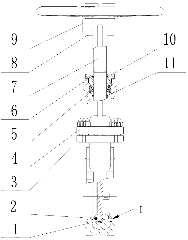
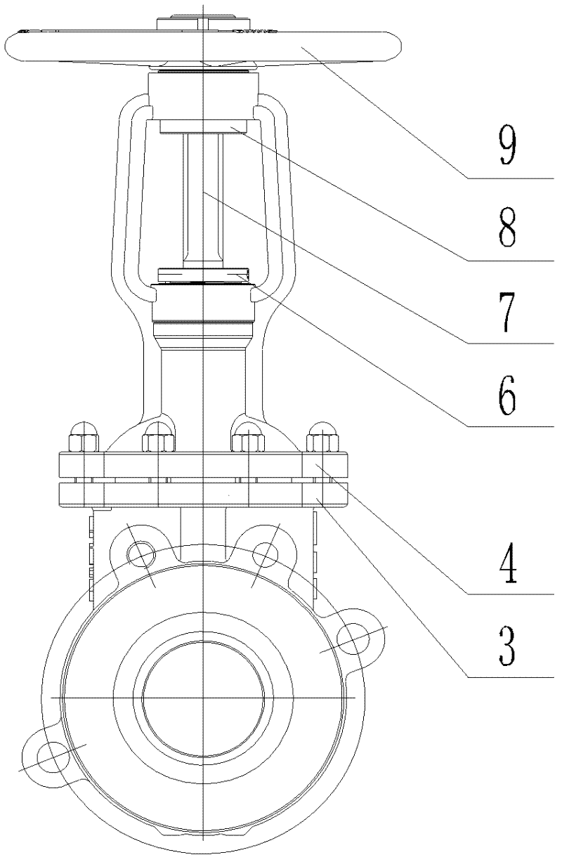
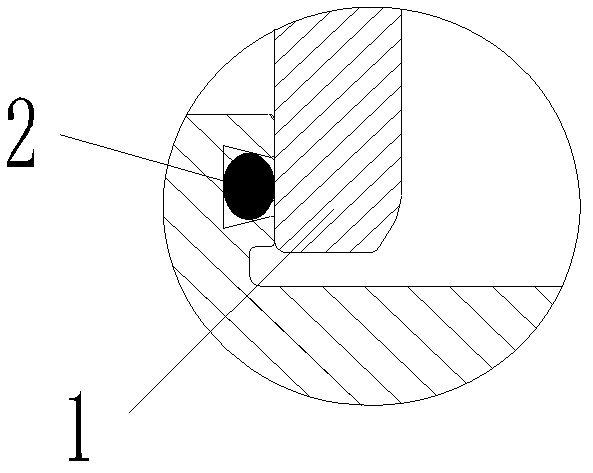
[0028] see Figure 1~3 , the embodiment of the present invention is provided with knife plate (gate) 2, valve body 3, valve cover 4, packing 5, packing gland 6, valve stem (shaft) 7, axle sleeve 8 and handwheel 9; Said valve body 3 and the valve cover 4 are fixedly connected, the knife plate (gate) 2 is installed in the inner cavity of the valve body 3 and the valve cover 4, the movement of the knife plate (gate) 2 is driven by the valve stem (shaft) 7, and the knife plate ( The trajectory of the gate) 2 is determined by the guide groove in the valve body 3; the valve stem (shaft) 7 is hingedly connected with the knife plate (gate) 2, the valve stem (shaft) 7 is provided with a groove, and the knife plate ( The gate plate) 2 is inserted into the slot, the bonnet 4 is provided with a bonnet stuffing box, the bonnet stuffing box is filled with filler 5 and pressed by the packing gland 6, and the valve stem (shaft) 7 passes through the bonnet stuffing box and the packing gland 6...
PUM
Abstract
The invention relates to a slurry gate valve and relates to a valve. The slurry gate valve is provided with a cutting board, a valve body, a valve cover, a stuffing, a stuffing gland, a valve rod, a shaft sleeve and a hand wheel, wherein the valve body is fixedly connected with the valve cover, the cutting board is arranged on an inner cavity of the valve body and the valve cover, the motion of the cutting board is driven by the valve rod, and the motion trail of the cutting board is determined by a guide groove in the valve body; the valve rod and the cutting board are connected by a hinge, the valve rod is provided with a notch, the cutting board is inserted into the notch, the valve cover is provided with a valve cover stuffing box, and the valve cover stuffing box is filled with the stuffing and is compacted by the stuffing gland; the valve rod passes through the valve cover stuffing box and the stuffing gland, the shaft sleeve is arranged on the valve cover, the shaft sleeve and the valve rod are in T-shaped thread fit and are fixed on the valve cover; and the hand wheel is arranged at the top of the valve rod. The slurry gate valve provided by the invention has the advantages of compact structure, small volume, light weight, convenience in transportation and installation, and effectively reduced material cost and the like; the slurry gate valve solves the serious problem that the conventional transporting-discharging paper pulp valve circulating channel is provided with a groove, is easily sitcked, is easy to scab, and is easily stuck by material; and the slurry gate valve is mainly used for papermaking slurry.
Description
technical field [0001] The invention relates to a valve, in particular to a pulp gate valve mainly used for papermaking pulp. Background technique [0002] Pulp gate valve is a commonly used valve for papermaking pulp. The existing pulp gate valve generally has the following deficiencies: [0003] 1) There are grooves in the flow channel, which are easy to store foreign matter, which will affect the opening and closing of the valve plate and cause leakage. [0004] 2) When the valve is opened, the sealing surface of the valve seat is directly washed by the fluid and is easily damaged. [0005] 3) The traditional knife gate valve has a large contact surface between the packing and the valve plate, and the friction force is relatively large. The operating force of the hand wheel is large, and the opening and closing is time-consuming and laborious. [0006] 4) The service life is short, the maintenance is frequent, and the production cost is increased. Contents of the inve...
Claims
Application Information
Patent Timeline
Application Date:The date an application was filed.
Publication Date:The date a patent or application was officially published.
First Publication Date:The earliest publication date of a patent with the same application number.
Issue Date:Publication date of the patent grant document.
PCT Entry Date:The Entry date of PCT National Phase.
Estimated Expiry Date:The statutory expiry date of a patent right according to the Patent Law, and it is the longest term of protection that the patent right can achieve without the termination of the patent right due to other reasons(Term extension factor has been taken into account ).
Invalid Date:Actual expiry date is based on effective date or publication date of legal transaction data of invalid patent.