
Laser-based deformation displacement measurement method

A deformation displacement and displacement measurement technology, which is applied in the direction of measuring devices, optical devices, instruments, etc., can solve the problems of large error, difficulty of two displacement values, complex errors of measuring devices, etc.

Active Publication Date: 2012-06-20
贵州省质安交通工程监控检测中心有限责任公司
View PDF7 Cites 17 Cited by
  • Summary
  • Abstract
  • Description
  • Claims
  • Application Information

AI Technical Summary

Problems solved by technology

[0003] The existing deformation and displacement have the disadvantages of complex measuring devices and large errors. Some such as total stations and rangefinders are used for deformation and displacement monitoring. The accuracy of the equipment itself, especially the error of human operation during use It is inevitable;
[0004] In addition, the existing laser-based displacement detection method uses the method of directly measuring two displacement values ​​and then calculating the difference. Because in harsh environments, it is very difficult to measure more accurate two displacement values, especially easy Introduce errors such as installation errors of equipment, resulting in relatively large errors as a whole. Generally, the single error is about ±3mm, and even the measurement error is greater than the actual displacement.
[0005] For example, in tunnel construction at present, the displacement monitoring around the tunnel is mostly completed by the convergent gauge with steel ruler and the level gauge with hanging ruler. Since the material of the steel ruler is greatly affected by temperature changes, even if it is used for temperature correction (compensation) , there is still a large deviation, and this deviation is sometimes greater than the actual deformation displacement depending on the environment. Different people also have reading deviations at the same time; the third is due to the existence of the steel ruler, which interferes with the tunnel construction. When the steel ruler is hung between the measuring points, vehicles are prohibited from passing. Unable to collect deformation displacement data

Method used


Image

  • Laser-based deformation displacement measurement method
  • Laser-based deformation displacement measurement method
  • Laser-based deformation displacement measurement method

Examples


Embodiment 1

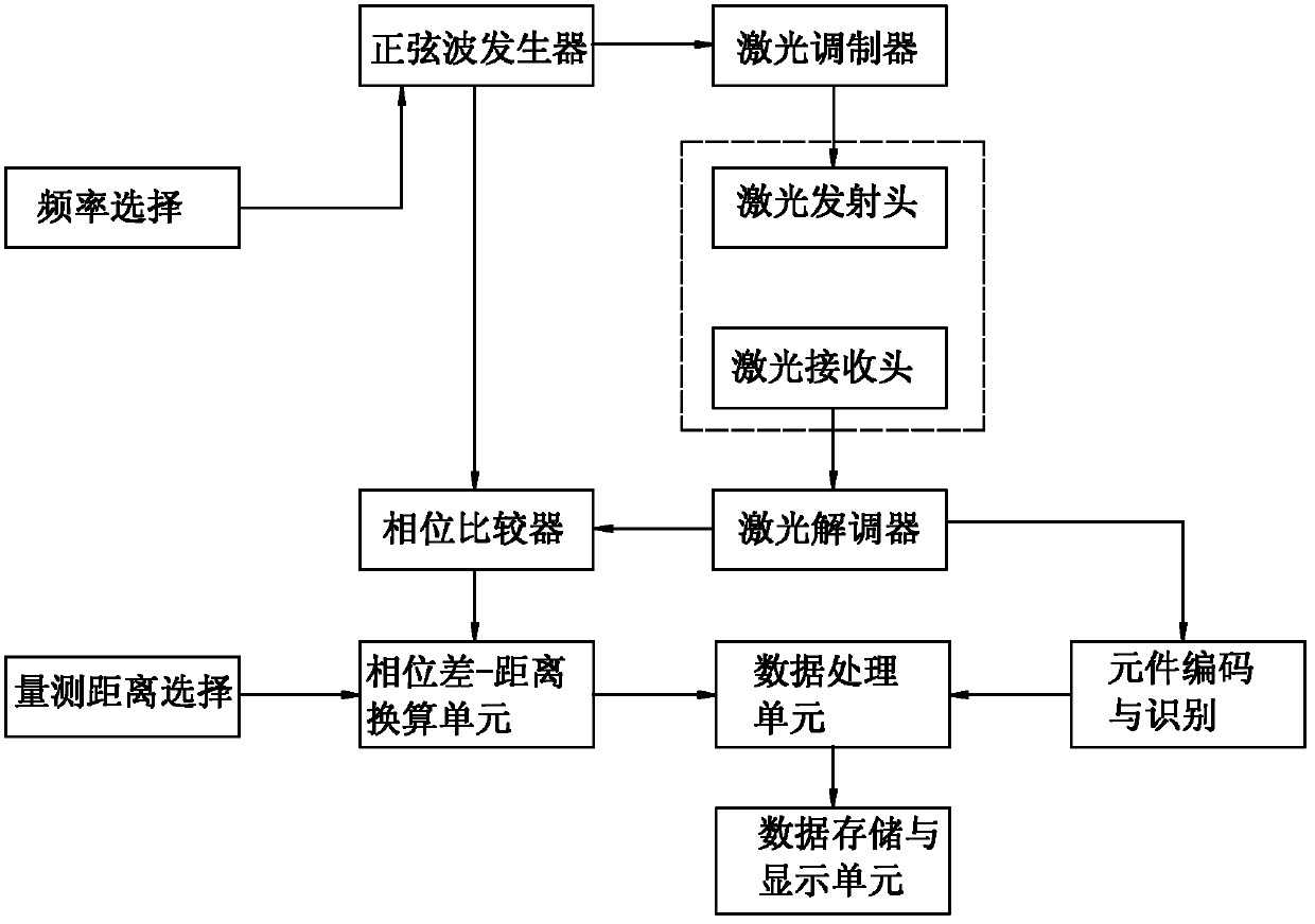
[0076] A laser-based deformation displacement measurement method, comprising the following steps:

[0077] Step 1: Preparatory work: install a reflector on the target to be measured, and set the modulation frequency of the laser;

[0078] Step 2: Obtain 2 phase difference values: Obtain T according to the phase difference acquisition step 0 time phase difference and T 1 time phase difference T 0 moment and t 1 Time refers to the time when the reflected laser light is received;

[0079] Step 3: Calculate the deformation displacement ΔL:

[0080] The formula for calculating ΔL is where K=c / (4πf);

[0081] The step of obtaining the phase difference is as follows: the laser emitting head of the displacement measuring instrument emits a beam of laser light with the modulation frequency, that is, the incident laser light; the electrical signal that excites the incident laser light is the first sinusoidal signal;

[0082] The beam of laser light is reflected by the reflec...


PUM


Abstract

The invention discloses a laser-based deformation displacement measurement method, comprising the following steps of: step 1, preparatory work: arranging a reflecting mirror on an object to be detected, and setting a laser modulation frequency; step 2, acquisition of two phase differences: acquiring the phase difference delta of time T0 and the phase difference delta of time T1 according to a phase difference acquisition step, wherein the time T0 and the time T1 both indicate the time of receiving reflected laser; and step 3, calculating a deformation displacement amount delta L, the calculation formula of delta L=K*(delta-delta), wherein K=c / (4pi*f). The method disclosed by the invention is easy in implementation and high in precision.

Description

technical field [0001] The invention relates to a method for measuring deformation displacement based on laser. Background technique [0002] Deformation displacement measurement plays an important role in both scientific and technological research and engineering construction: horizontal and vertical displacement of dams, displacement around tunnels, horizontal and vertical displacements of structures, etc. The method of deformation displacement measurement can be accomplished by laser distance meter, total station, digital (traditional) theodolite. [0003] The existing deformation and displacement have the disadvantages of complex measuring devices and large errors. Some such as total stations and rangefinders are used for deformation and displacement monitoring. The accuracy of the equipment itself, especially the error of human operation during use It is inevitable; [0004] In addition, the existing laser-based displacement detection method uses the method of directl...

Claims


Application Information

Patent Timeline
IPC IPC(8): G01B11/02G01B11/16
Inventor 邱业建彭立敏施成华雷明锋杨伟超
Owner 贵州省质安交通工程监控检测中心有限责任公司
Learn More