Heliostat angle deviation detection method for tower type solar thermal power generation system
A tower type solar energy and thermal power generation system technology, applied in the field of heliostat angle deviation detection, can solve the problems of heat absorbers that cannot contribute heat, errors, etc.
- Summary
- Abstract
- Description
- Claims
- Application Information
AI Technical Summary
Problems solved by technology
Method used
Image


Examples
Embodiment 1
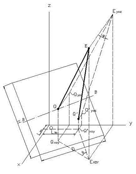
[0077] control Figure 5 , the tower solar thermal power generation system includes a tower T, a heat absorber H and a heliostat M. The first imaging unit E is fixed on the central area of the heat absorber H on the tower T, and several heliostats are arranged under the tower according to the setting method to form a mirror field (it is possible that several heat absorbers H are fixed around the tower T, and the mirror field The sub-rings are distributed around the lower part of the tower, and each heat absorber corresponds to a part of the mirror field. This embodiment takes a heat absorber and the corresponding mirror field as an example). k-th heliostat M k The mirror faces the heat absorber H, and forms a light spot on the heat absorber by reflecting the sun's rays. The heliostat M k The position is fixed and can be rotated horizontally and vertically. The axis Z of the horizontal rotation and the axis X of the vertical rotation pass through the mirror center Q k . ...
Embodiment 2
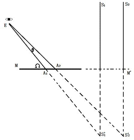
[0084]This embodiment is based on the fact that the first lens E in the above embodiments is located in the central area of the heat absorber, which will affect the heat absorption effect, and the temperature is very high, which will affect the life of the lens. Therefore, in this embodiment, several second lenses, second cameras, or several second cameras are provided on the basis of the foregoing embodiments. Distribute several second lenses F around the periphery of the heat sink to form a "fence", see Figure 11 , the distance between the two second lenses F is smaller than the width or height of the minimum reflected light spot. Therefore, the imaging unit of this embodiment actually includes two parts, the first imaging unit and the second imaging unit consisting of several second lenses, second cameras or several second cameras and a computer.
[0085] Initially use the first imaging unit and the second imaging unit to take pictures of the corresponding mirror fields...
Embodiment 3
[0090] This embodiment is a method for correcting errors caused by movement when the imaging unit in the above embodiments moves relative to the mirror field.
[0091] The movement of the first imaging unit will cause imaging deviation, that is, the images formed after the two movements are different, which will directly affect the accuracy of the calibration; strong wind or mechanical reasons will also cause the images of the first and second imaging units error. The following method can be used to solve this problem: install no less than 3 controllable laser emitters (or high-brightness light-emitting devices) that are not in a straight line at some fixed positions without heliostats in the mirror field, and the beams emitted by them can The first and second imaging units are covered, and the light emitting frequency of the controllable laser emitter or the high brightness light emitting device corresponds to the shooting time interval. Use the first imaging unit and the se...
PUM
 Abstract
Description
Claims
Application Information
 - R&D
- Intellectual Property
- Life Sciences
- Materials
- Tech Scout
- Unparalleled Data Quality
- Higher Quality Content
- 60% Fewer Hallucinations
Browse by: Latest US Patents, China's latest patents, Technical Efficacy Thesaurus, Application Domain, Technology Topic, Popular Technical Reports.
© 2025 PatSnap. All rights reserved.Legal|Privacy policy|Modern Slavery Act Transparency Statement|Sitemap|About US| Contact US: help@patsnap.com