Method for checking vibration fault of fan blade of aerial engine

An aero-engine and fan blade technology, applied in the field of aero-engine, can solve problems such as unusability, and achieve the effect of overcoming limitations, improving reliability and maintainability

Inactive Publication Date: 2012-06-20
NORTHWESTERN POLYTECHNICAL UNIV
View PDF10 Cites 28 Cited by
  • Summary
  • Abstract
  • Description
  • Claims
  • Application Information

AI Technical Summary

Problems solved by technology

However, the non-contact blade vibration test principle determines that the non-contact probe m

Method used


Image

  • Method for checking vibration fault of fan blade of aerial engine
  • Method for checking vibration fault of fan blade of aerial engine
  • Method for checking vibration fault of fan blade of aerial engine

Examples


Embodiment 1

[0042] This embodiment is a method for detecting flutter faults of fan blades of a certain type of aeroengine.

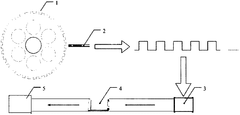
[0043] The measurement principle of this embodiment is as figure 1 shown. The detection device used is composed of a speed measuring toothed disc 1 , an eddy current displacement sensor 2 , a signal conditioner 3 , a data acquisition card 4 and a computer 5 .

[0044] The speed-measuring toothed disc 1 is an existing component on the fan rotor of the aero-engine, and rotates with the engine rotor; the number of teeth of the speed-measuring toothed disc 1 is N=36. The eddy current displacement sensor 2 is installed at the radial or axial position of the speed measuring toothed disc 1 and aligned with any tooth of the speed measuring toothed disc 1 . The eddy current displacement sensor 2 is connected to the signal conditioner 3 through a vibration signal transmission line. The data acquisition card 4 is integrated with the signal conditioner 3, and the signal cond...

Embodiment 2

[0076] This embodiment is a method for detecting flutter faults of fan blades of a certain type of aeroengine.

[0077] The measurement principle of this embodiment is as figure 1 shown. The detection device used is composed of a speed measuring toothed disc 1 , an eddy current displacement sensor 2 , a signal conditioner 3 , a data acquisition card 4 and a computer 5 .

[0078] The speed-measuring toothed disc 1 is an existing component on the fan rotor of the aero-engine, and rotates with the engine rotor; the number of teeth of the speed-measuring toothed disc 1 is N=34. The eddy current displacement sensor 2 is installed at the radial or axial position of the speed measuring toothed disc 1 and aligned with any tooth of the speed measuring toothed disc 1 . The eddy current displacement sensor 2 is connected to the signal conditioner 3 through a vibration signal transmission line. The data acquisition card 4 is integrated with the signal conditioner 3, and the signal cond...


PUM


Abstract

The invention relates to a method for checking vibration fault of a fan blade of an aerial engine. The method comprises the following steps of: measuring torsion vibration of the aerial engine by utilizing a speed measuring fluted disc, an eddy current displacement sensor, a signal conditioner, a data acquisition card and a computer, and carrying out real-time monitoring on the torsion vibration under the conditions of aerial engine ground bench test drive, vehicle-mounted ground test drive and maneuver flight. The reliability and maintenance of the engine are improved by detecting the fan blade vibration characteristic frequency contained in a rotor torsion vibration signal, judging an aeroelectric state of the fan blade and diagnosing the vibration fault of the blade of the aerial engine. According to the method for checking the vibration fault of the fan blade of the aerial engine, disclosed by the invention, a torsion vibration signal is measured directly from an aerial engine shaft system so that the fault information of vibration can be clearly reflected, the elements of the torsion vibration signal obtained through measurement are simple and are convenient to analyze, the engineering limitation of a current conventional measurement method is overcome, and the real-time monitoring of the vibration of the fan blade is ensured to be carried out under various conditions, such as the engine ground bench test drive, the vehicle-mounted ground test drive, the maneuver flight and the like.

Description

technical field [0001] The invention relates to the field of aero-engines, in particular to a method for monitoring flutter faults of engine fan blades. Background technique [0002] Blade flutter is a common problem in engine operation. Flutter is a typical aeroelastic instability phenomenon that occurs when the lift system is near the stall angle of attack. The high-frequency vibration of the blade caused by the flutter problem often causes fatigue damage. The flutter fatigue failure is due to the elastic coupling between the blade and the blade under certain conditions, resulting in the fatigue failure caused by the phenomenon of aeroelastic instability. Flutter fatigue failure belongs to low cycle fatigue failure, the stress level of failure is high, and the number of fatigue cycles of damage is low. Once the engine fan blade flutters, if it is not detected and controlled in time, it will often cause damage to the blade in a short period of time, resulting in disastrous...

Claims


Application Information

Patent Timeline
IPC IPC(8): G01M15/12G01M13/00
Inventor 廖明夫王俨剀王四季蒋云帆
Owner NORTHWESTERN POLYTECHNICAL UNIV
Why Eureka
Try Eureka