Method for checking vibration fault of fan blade of aerial engine
An aero-engine and fan blade technology, applied in the field of aero-engine, can solve problems such as unusability, and achieve the effect of overcoming limitations, improving reliability and maintainability
- Summary
- Abstract
- Description
- Claims
- Application Information
AI Technical Summary
Problems solved by technology
Method used
Image
Examples
Embodiment 1
[0042] This embodiment is a method for detecting flutter faults of fan blades of a certain type of aeroengine.
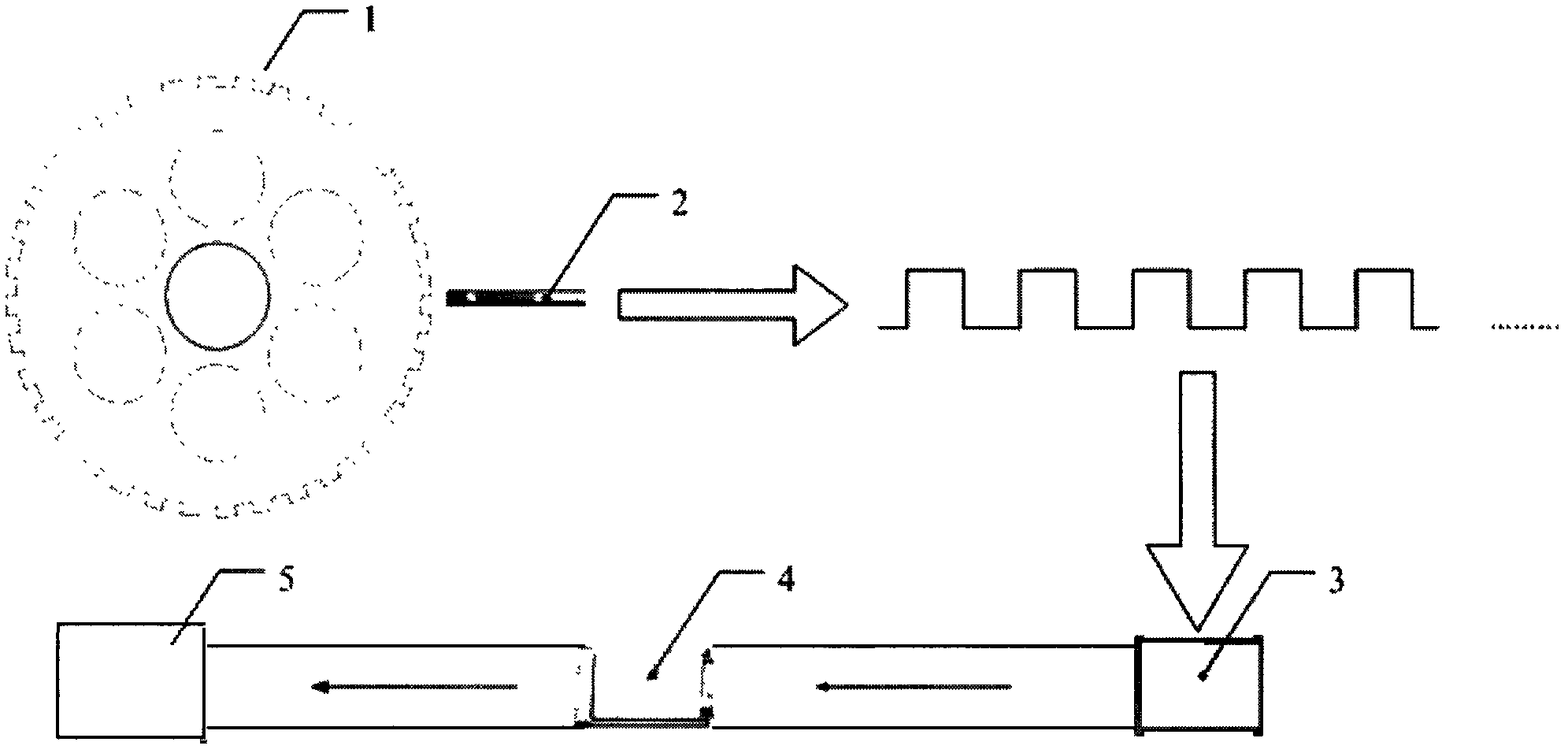
[0043] The measurement principle of this embodiment is as figure 1 shown. The detection device used is composed of a speed measuring toothed disc 1 , an eddy current displacement sensor 2 , a signal conditioner 3 , a data acquisition card 4 and a computer 5 .
[0044] The speed-measuring toothed disc 1 is an existing component on the fan rotor of the aero-engine, and rotates with the engine rotor; the number of teeth of the speed-measuring toothed disc 1 is N=36. The eddy current displacement sensor 2 is installed at the radial or axial position of the speed measuring toothed disc 1 and aligned with any tooth of the speed measuring toothed disc 1 . The eddy current displacement sensor 2 is connected to the signal conditioner 3 through a vibration signal transmission line. The data acquisition card 4 is integrated with the signal conditioner 3, and the signal cond...
Embodiment 2
[0076] This embodiment is a method for detecting flutter faults of fan blades of a certain type of aeroengine.
[0077] The measurement principle of this embodiment is as figure 1 shown. The detection device used is composed of a speed measuring toothed disc 1 , an eddy current displacement sensor 2 , a signal conditioner 3 , a data acquisition card 4 and a computer 5 .
[0078] The speed-measuring toothed disc 1 is an existing component on the fan rotor of the aero-engine, and rotates with the engine rotor; the number of teeth of the speed-measuring toothed disc 1 is N=34. The eddy current displacement sensor 2 is installed at the radial or axial position of the speed measuring toothed disc 1 and aligned with any tooth of the speed measuring toothed disc 1 . The eddy current displacement sensor 2 is connected to the signal conditioner 3 through a vibration signal transmission line. The data acquisition card 4 is integrated with the signal conditioner 3, and the signal cond...
PUM
 Abstract
Description
Claims
Application Information
 - R&D
- Intellectual Property
- Life Sciences
- Materials
- Tech Scout
- Unparalleled Data Quality
- Higher Quality Content
- 60% Fewer Hallucinations
Browse by: Latest US Patents, China's latest patents, Technical Efficacy Thesaurus, Application Domain, Technology Topic, Popular Technical Reports.
© 2025 PatSnap. All rights reserved.Legal|Privacy policy|Modern Slavery Act Transparency Statement|Sitemap|About US| Contact US: help@patsnap.com


