
Plating surface wear resistance tester

A wear-resistant test and electroplating technology, which is applied in the direction of test wear resistance, etc., can solve the problems of inaccurate test results, noise, etc., and achieve the effect of good versatility, improved accuracy, and smooth grinding

Inactive Publication Date: 2012-06-20
WENZHOU YIHUA CONNECTOR
View PDF5 Cites 15 Cited by
  • Summary
  • Abstract
  • Description
  • Claims
  • Application Information

AI Technical Summary

Problems solved by technology

[0003] For this reason, the technical problem to be solved by the present invention is that the structural design between the grinding head and the gravity weight of the wear resistance tester in the prior art is unreasonable, which leads to the generation of noise in the test process, and the inaccurate test results. To solve the problem, provide a wear-resistant testing machine for the surface of the electroplating layer that has no noise during the test and has accurate test results.

Method used


Image

  • Plating surface wear resistance tester
  • Plating surface wear resistance tester
  • Plating surface wear resistance tester

Examples


Embodiment 1

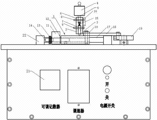
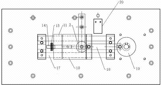
[0027] Such as Figure 1-2 As shown, a kind of electroplating surface wear-resisting testing machine of embodiment 1 comprises sample loading platform 1, and described sample loading platform 1 can fix the sample to be tested; Grinding mechanism, described grinding mechanism is arranged on described loading by support Above the sample stage 1, it includes a sleeve 2 installed on the support, a grinding head 3 installed on the sleeve 2 and a gravity weight 4, and the gravity weight 4 is arranged on the grinding head 3 Above, the grinding head 3 is loaded, of course, the support can be set as a structure adjustable up and down; the driving mechanism, the driving mechanism drives the sample loading table 1 or the grinding mechanism to move back and forth relatively, The reciprocating sliding friction is generated between the grinding head 3 and the sample to be tested; the lower end of the gravity weight 4 has a fixed rod 5, and the upper end of the sleeve 2 is suitable for inser...

Embodiment 2

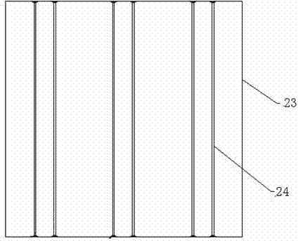
[0036] Such as image 3 As shown, when the sample to be tested is a metal wire 24 provided with an electroplated layer, the snap-in groove 12 of the sample loading platform 1 is also provided with a detachable substrate on which the metal wire 24 is fixed. . In this embodiment, the substrate is a copper sheet 23, and the metal wire 24 is fixed on the substrate by welding. The metal wire can be palladium gold wire or gold wire or the like.

Embodiment 3

[0038] Such as Figure 4 As shown, of course, the substrate can also be punched, thereby directly forming several metal wires 24 on the substrate, and then an electroplating layer is arranged on the formed metal wires 24, and finally the substrate is arranged on the sample stage. Available for testing. In this embodiment, the base may be a copper sheet 23 .

[0039] Working process of the present invention:

[0040] The invention can not only be used to test the wear resistance of the object plane, but also can test the wear resistance of tiny coated wires, such as palladium gold wire or gold wire. Only when testing the wear resistance of the plane of the item, the test item can be directly clamped on the sample loading platform 1; when testing the coated wire, it is necessary to fix the electroplated coated wire, such as palladium gold wire or gold wire, on the On the copper sheet 23, load it on the sample loading platform 1 again, and align the palladium wire for the wear...


PUM


Abstract

The invention relates to a plating surface wear resistance tester, which comprises a sample carrying platform, a grinding mechanism, a driving mechanism and a limiting connector, wherein the grinding mechanism is arranged above the sample carrying platform by a support and comprises a sleeve which is arranged on the support and a grinding head and a weight which are arranged on the sleeve; the weight is arranged above the grinding head and adds a load onto the grinding head; the driving mechanism drives the sample carrying platform or the grinding mechanism to do reciprocal movement so that reciprocal sliding friction is generated between the grinding head and a sample to be tested; the lower end of the weight is provided with a fixed rod, and the upper end of the sleeve is suitable for the fixed rod to be inserted into; the lower end of the sleeve is suitable for the upper end of the grinding head to be inserted into; a shock absorbing device is arranged between the upper end of the grinding head and the fixed rod; and the limiting connector is used for connecting the fixed rod and the grinding head to the sleeve respectively and allowing the fixed rod and the grinding head to make up and down displacement along the axial direction of the sleeve. The plating surface wear resistance tester can operate quietly in a test process and delivers an accurate test result.

Description

technical field [0001] The invention relates to an abrasion-resistant testing machine, in particular to an electroplating surface abrasion-resistant testing machine. Background technique [0002] At present, there are many wear-resistant performance testers for testing the electroplating layer on the surface of an object, such as a kind of wear-resistant tester disclosed in Chinese patent document CN200965503Y, which includes a sample loading table that can fix the sample, and can be fixed on the loading table within a certain distance. The test head on the sample platform is kept in sliding contact, and the power device that can drive the test head or the sample loading platform to make the two reciprocate and move relative to each other. During the reciprocating relative movement of the two, the test head keeps sliding contact with the sample on the sample loading platform to generate friction and complete the test action. The prior art has good repeatability, can avoid t...

Claims


Application Information

Patent Timeline
Patent Type & Authority Applications(China)
IPC IPC(8): G01N3/56
Inventor 陈建新
Owner WENZHOU YIHUA CONNECTOR
Learn More