Dry-hole pressure relief valve and hydraulic fracturing crustal stress testing device

The technology of a test device and a pressure relief valve is applied in the direction of a measuring device, a force/torque/work measuring instrument, a force sensor in a hole of a force-bearing structure, etc., which can solve problems such as the complexity of the test equipment, and achieve simple structure and high test efficiency. Stable, easy-to-operate effect

Pending Publication Date: 2017-10-10
INST OF ROCK & SOIL MECHANICS CHINESE ACAD OF SCI
View PDF12 Cites 12 Cited by
  • Summary
  • Abstract
  • Description
  • Claims
  • Application Information

AI Technical Summary

Problems solved by technology

[0006] 2. Double-tube pressurization, specifically, one high-pressure tube is used to pressurize the capsule (air pressure), and the other high-pressure tube is used to pressurize the test section (water pressure). The main problems of this double-tube pressurization are: the test equipment is complicated , The pressure sensor should be placed on the upper end of the packer (to reduce the pressure error)

Method used


Image

  • Dry-hole pressure relief valve and hydraulic fracturing crustal stress testing device
  • Dry-hole pressure relief valve and hydraulic fracturing crustal stress testing device
  • Dry-hole pressure relief valve and hydraulic fracturing crustal stress testing device

Examples


no. 1 example

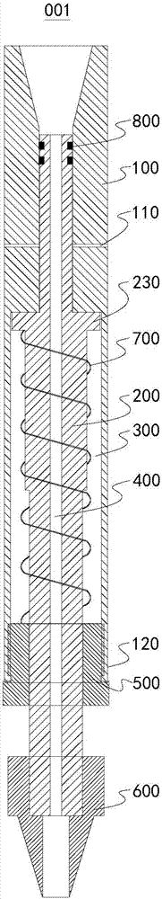
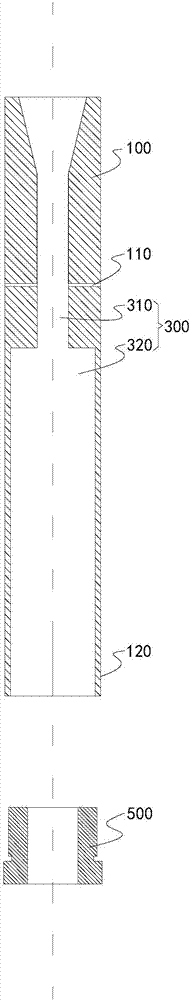
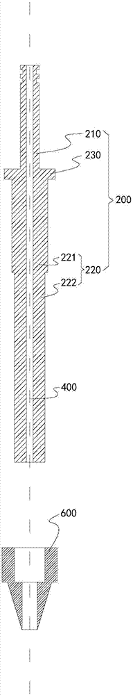
[0034] Please refer to Figure 1 to Figure 3 As shown, this embodiment provides a dry hole pressure relief valve 001, which includes a valve body 100 and a valve core 200. The valve body 100 has a valve cavity 300 that is arranged along its axis and is penetrated. The valve core 200 has a valve body that is arranged along its axis. The valve core 200 is inserted into the valve cavity 300 by the insertion end 120 of the valve body 100, and one end extends from the insertion end 120. There is a gap between the valve core 200 and the valve body 100, and the valve body 100 is far away from the insertion end. One end of 120 communicates with one end of the valve core 200 through the valve cavity 300, and then communicates with the end of the valve core 200 protruding from the insertion end 120 through the through hole 400 to realize the communication between the two ends of the dry hole pressure relief valve 001. The valve 001 is installed on the drill pipe, and the packer capsule c...

no. 2 example

[0041] Please refer to Figure 4 As shown, this embodiment provides a hydraulic fracturing in-situ stress testing device 002, which includes a collector 023, a high-pressure pump 010, a switching valve 020, and an elevator 017, which is suspended below the elevator 017 and inserted downward into the borehole The drill rod 018 in the borehole 019 and the packer 021 in the borehole 019. The high-pressure pump 010 communicates with the top end of the borehole 019. The bottom end of the borehole 019 is connected to the dry hole pressure relief valve 001 in the first embodiment. The top end is connected, the bottom end of the dry hole pressure relief valve 001 is connected to the top end of the switching valve 020, and the bottom end of the switching valve 020 is connected to the packer 021.

[0042] In this embodiment, the dry hole pressure relief valve 001 is arranged vertically, the top end of the dry hole pressure relief valve 001 is the end far from the insertion end 120, and the ...


PUM


Abstract

The invention discloses a dry-hole pressure relief valve and a hydraulic fracturing crustal stress testing device, and relates to the technical field of rock mass engineering testing. A valve core of the dry-hole pressure relief valve is inserted in a valve cavity from the insertion end of a valve body, and one end of the valve core extends out of the insertion end; a plurality of pressure relief holes are formed in the end, away from the insertion end, of the valve body, the valve core is provided with a blocking part which can block the valve cavity, and the insertion end of the valve body is provided with a limit nut for limiting the length of the part, extending out of the valve body, of the valve core; the part, located between the blocking part and the limit nut, of the valve core is sleeved with a load-bearing spring; the dry-hole pressure relief valve is simple in structure and convenient to operate, and can effectively relieve pressure in a packer. A high-pressure pump of the hydraulic fracturing crustal stress testing device is communicated with the top end of a drilling hole, the bottom end of the drilling hole is communicated with the dry-hole pressure relief value, the end, extending out of the insertion end, of the valve core is communicated with a switching valve, and the switching valve is communicated with the packer. Through the adoption of the hydraulic fracturing crustal stress testing device, crustal stress tests can be conducted under the conditions of deep drilling holes and dry holes by using a hydraulic fracturing method, and the tests are stable.

Description

Technical field [0001] The invention relates to the technical field of rock mass engineering testing, in particular to a dry hole pressure relief valve and a hydraulic fracturing ground stress testing device. Background technique [0002] In-situ stress is the natural stress existing in the stratum. It is the fundamental force that causes the deformation and destruction of mine roadways and other underground projects. Therefore, the magnitude and direction of the in-situ stress directly affect the stability of the surrounding rock of the roadway. Stress, studying the stress distribution characteristics of surrounding rock is a necessary prerequisite for the stability analysis of the surrounding rock of the roadway and the realization of scientific underground engineering excavation design. At present, the testing methods of engineering rock in-situ stress modulus commonly used internationally can be summarized as: surface stress relief method, surface stress recovery method, casi...

Claims


Application Information

Patent Timeline
Patent Type & Authority Applications(China)
IPC IPC(8): G01L5/00
CPCG01L5/0004
Inventor 罗超文李海波李俊如刘亚群刘博周青春夏祥余崇邓守春
Owner INST OF ROCK & SOIL MECHANICS CHINESE ACAD OF SCI
Why Eureka
Try Eureka