Anvil cell high pressure device for in situ neutron diffraction

A high-pressure device and an anvil technology, applied in the field of in-situ neutron diffraction experiments, can solve problems such as failure of experiments, inability to test samples with hydraulic loading and pressure, and difficulty in ensuring sample preloading pressure, etc., to achieve good retention and increase flexibility Effect

Active Publication Date: 2012-06-20
SICHUAN UNIV
View PDF4 Cites 30 Cited by
  • Summary
  • Abstract
  • Description
  • Claims
  • Application Information

AI Technical Summary

Problems solved by technology

[0004] Aiming at the deficiencies of the prior art in-situ neutron diffraction counter-anvil high-voltage device, the purpose of the present invention is to provide a new structure of the in-situ neutron diffraction counter-anvil high-voltage device to solve the problem of prior art in-situ A counter-anvil high-pressure device for neutron diffraction generally can only be used for an anvil made of one material, and cannot be used for real-time hydraulic loading of experimental samples on the test bench. It is difficult to ensure that the samples are preloaded. Experiments are carried out under pressure, which can easily lead to problems such as experiment failure

Method used


Image

  • Anvil cell high pressure device for in situ neutron diffraction
  • Anvil cell high pressure device for in situ neutron diffraction
  • Anvil cell high pressure device for in situ neutron diffraction

Examples


Embodiment 1

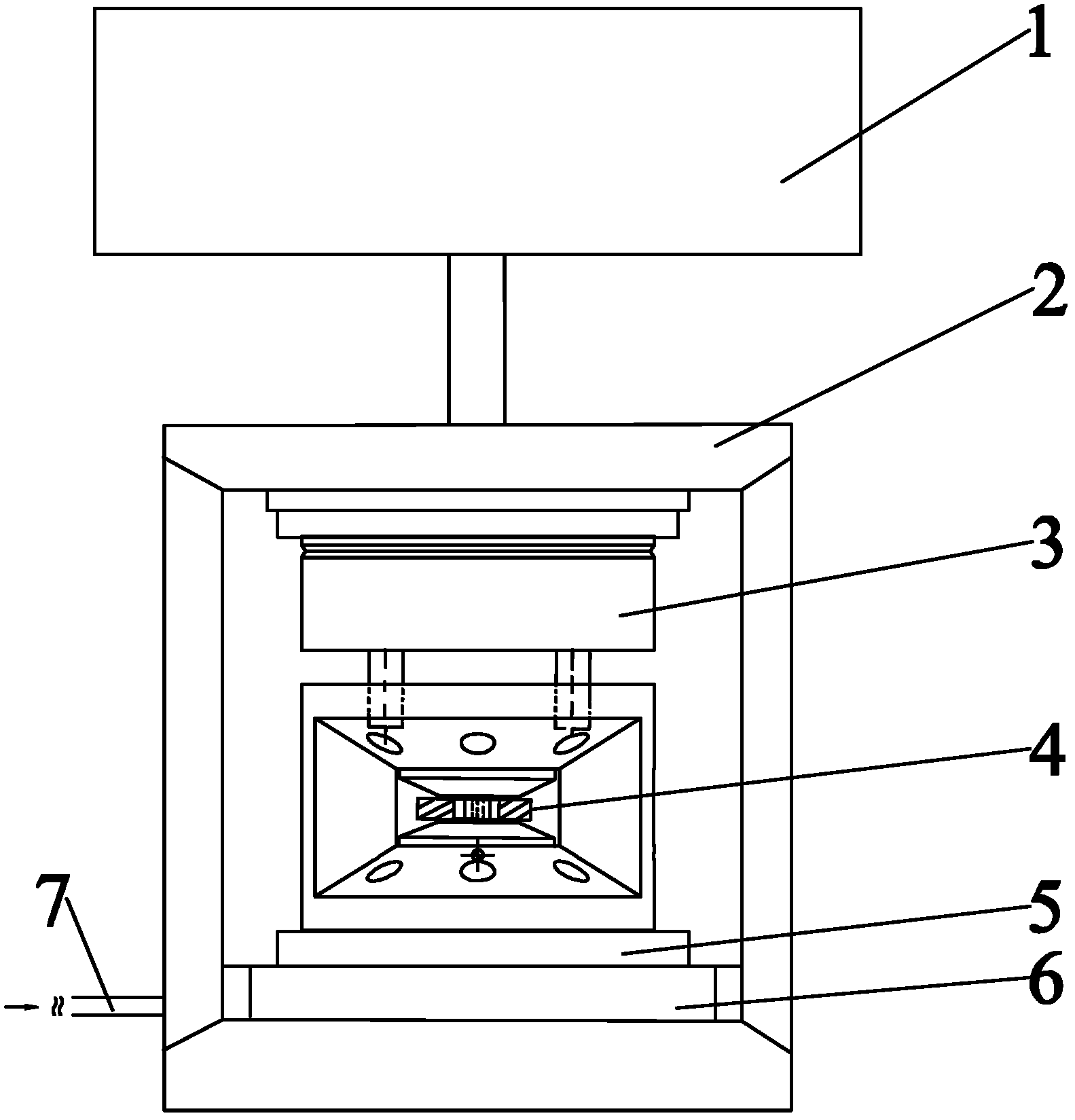
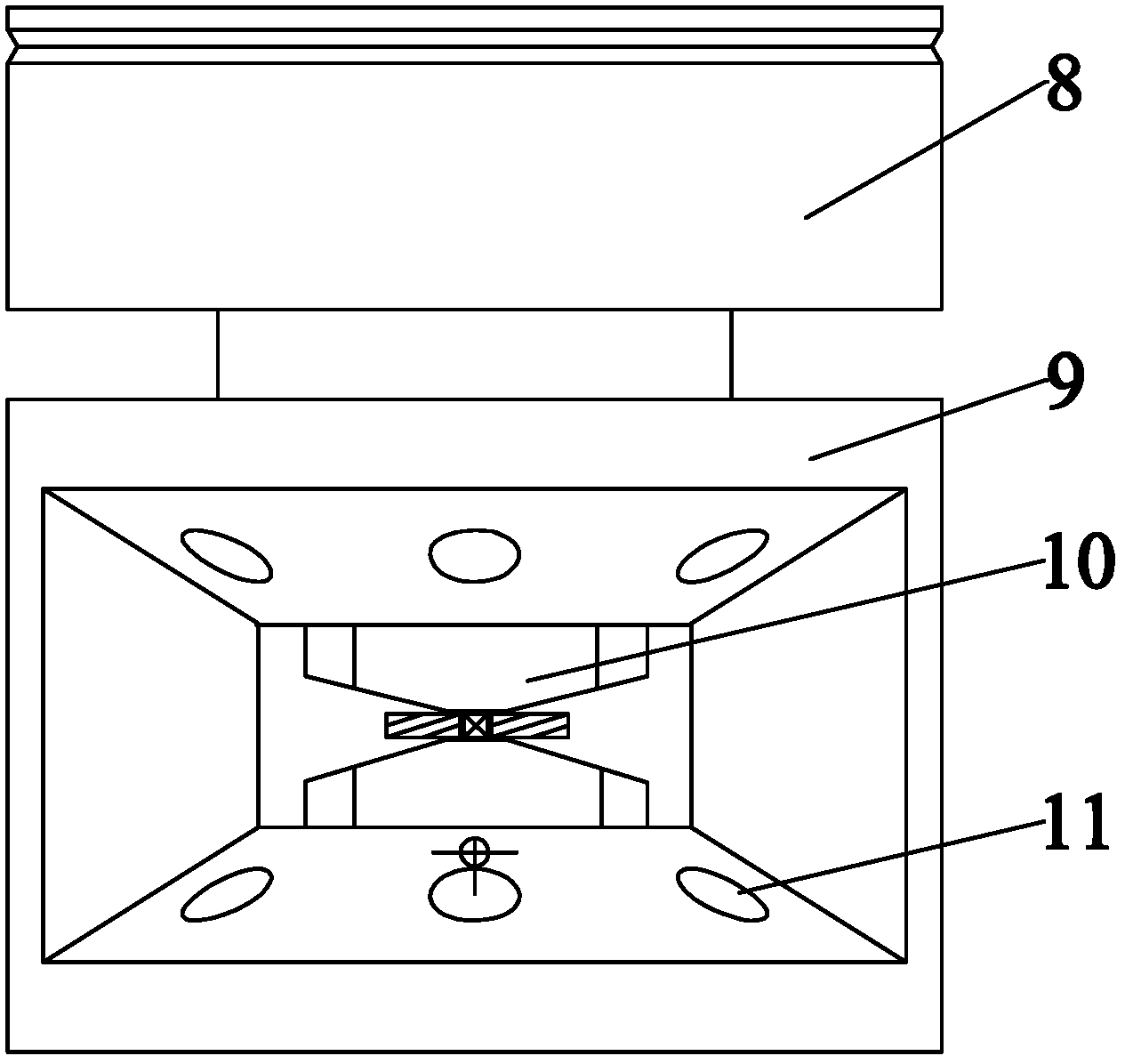
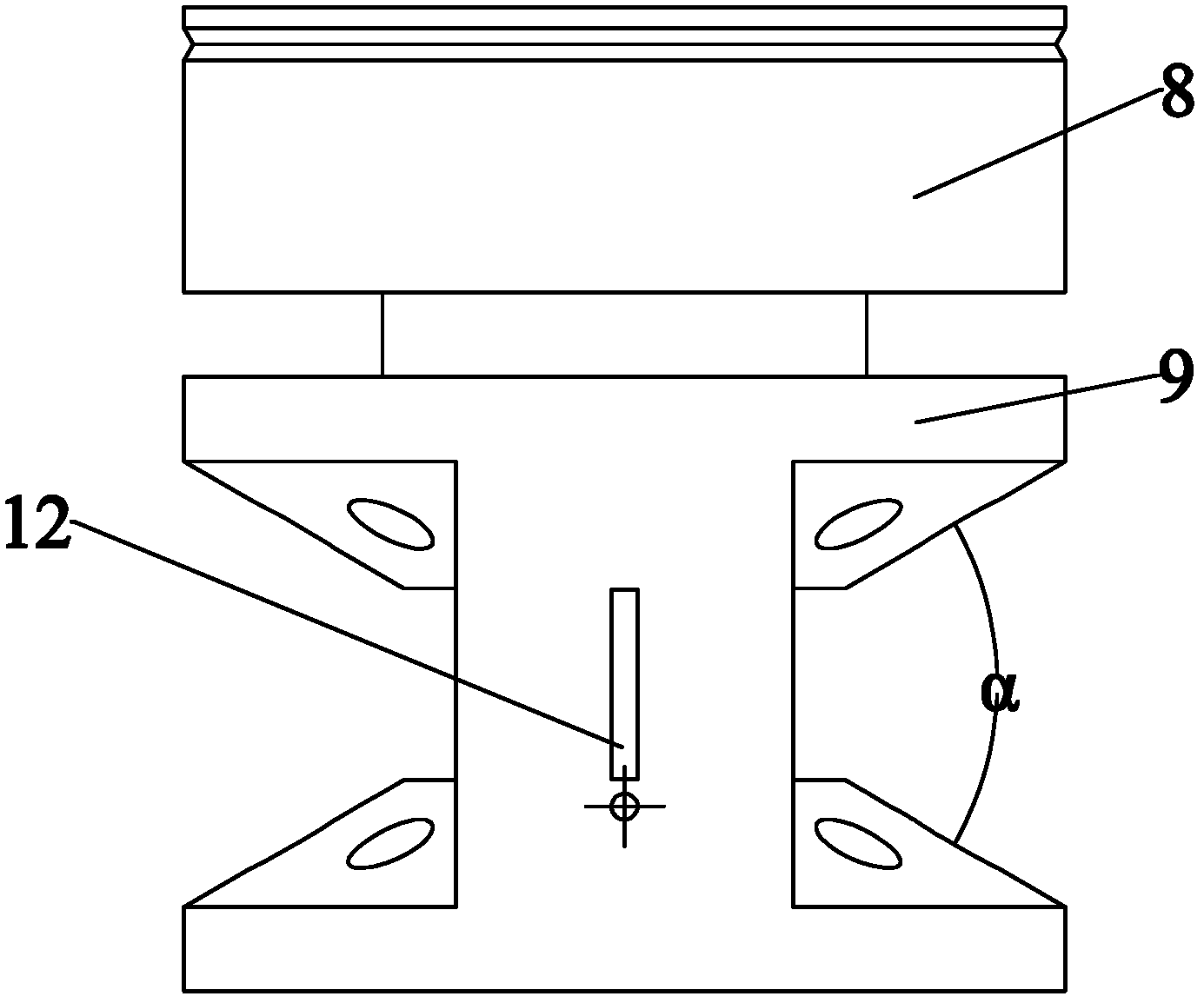
[0031] The in-situ neutron diffraction of the present embodiment uses the anvil high pressure device, and its structure is as attached figure 1 As shown in accompanying drawing 4, it is composed of a body device and a suspension device 1. The body device is provided with a two-stage pressure loading subsystem, consisting of a frame 2, a hydraulic loading subsystem located in the frame, and an internal pressure chamber 3 located in the internal pressure Two anvils 10 opposite to each other in the cavity, a gasket 21 between the two anvils, and a reinforcement ring 20 outside the anvils 10 constitute a mechanical loading subsystem attached to the internal pressure cavity. In the hydraulic secondary loading subsystem, the piston cylinder 6 is fixed on the frame 2, the piston 5 acts on the internal pressure chamber, and the piston cylinder is connected to the hydraulic press far away from the test bench through the high-pressure oil pipe 7. The components of the hydraulic secondary...


PUM


Abstract

The invention discloses an anvil cell high pressure device for the in situ neutron diffraction, which mainly comprises a frame, an inner pressure cavity, pressing anvils, a sealing cushion and a loading system, wherein the inner pressure cavity is positioned in the frame and is formed by a pressure head and a cavity seat; the pressing anvils are positioned in the inner pressure cavity and are respectively arranged on the pressure head and the cavity seat; anvil surfaces of the two pressing anvils are opposite; the sealing cushion is positioned between the two pressing anvils; a sample high pressure sealing cavity is formed by the two pressing anvils and the sealing cushion positioned between the two pressing anvils; the inner pressure cavity is provided with a neutron beam incident light channel and a diffraction light window; the loading system is provided with two stages of loading subsystems; primary loading subsystems are screw thread pair mechanical loading systems which are symmetrically arranged in pairs; a secondary load subsystem is formed by an oil cylinder arranged on the frame and a piston acts on the inner pressure cavity; and the high pressure device is suspended below a suspension device matched with a neutron reactor source platform through the frame. The anvil cell high pressure device has good compatibility between the pressing anvils and can be used for carrying out loading pressure application on an experimental sample on an experiment table. The loading pressure can be kept for a long time. Experimenters can be far away from the experiment table to carry out experimental operation. The anvil cell high pressure device has high safety.

Description

technical field [0001] The invention relates to in-situ neutron diffraction experiment technology, more specifically relates to an in-situ neutron diffraction counter-anvil high-pressure device for measuring material structure and physical properties under ultra-high pressure. technical background [0002] In the field of high-pressure technology, the counter-anvil type high-pressure device is an instrument that can generate ultra-high pressure. The gasket between them and the loading mechanism on the inner pressure chamber are set, the upper and lower anvils and the gasket constitute a high-pressure chamber for placing the sample to be tested, and a pressure-transmitting medium is filled around the sample in the high-pressure chamber. The pressure transmission medium can be solid, liquid or gas. Among them, the gas pressure transmission medium has the advantages of complete hydrostatic pressure transmission characteristics, stable chemical properties and the ability to with...

Claims


Application Information

Patent Timeline
Patent Type & Authority Applications(China)
IPC IPC(8): G01N23/20
Inventor 陆裕平贺端威惠博陈波孙光爱陈喜平
Owner SICHUAN UNIV
Why Eureka
Try Eureka