Data collection synchronous method of electrical railway distance measurement device

A technology of electrified railway and distance measuring device, which is applied in the direction of measuring device, measuring electricity, fault location, etc., to achieve the effect of high precision

Inactive Publication Date: 2012-06-20
NR ELECTRIC CO LTD +1
View PDF5 Cites 23 Cited by
  • Summary
  • Abstract
  • Description
  • Claims
  • Application Information

AI Technical Summary

Problems solved by technology

Solve the problem that the measured data transmission delay requires a bidirectional channel, so that each device needs two receiving and two sending optical fiber interfaces

Method used


Image

  • Data collection synchronous method of electrical railway distance measurement device
  • Data collection synchronous method of electrical railway distance measurement device
  • Data collection synchronous method of electrical railway distance measurement device

Examples


Embodiment Construction

[0012] The present invention will be described in further detail below in conjunction with the accompanying drawings and specific embodiments.

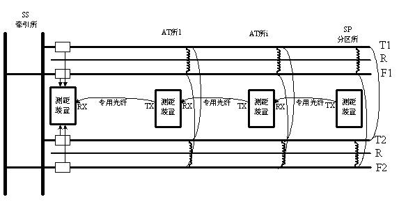
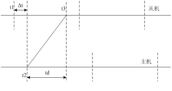
[0013] For the dedicated optical fiber synchronization method, the system architecture is as follows figure 1 As shown in the figure, the distance measuring device of a certain station is connected with the distance measuring device of the adjacent station on the side of the traction station with an optical fiber, and the optical fiber communication interfaces of the distance measuring devices of the entire distance measuring system are connected in series. Synchronous methods such as figure 2 As shown, t1 is the time when the slave sampling interrupt occurs, t2 is the time when the master sampling interrupt occurs, td is the delay of data transmission between the master and slave, ?t is the time difference between the master and slave sampling interruption, and ?t represents the Degree of out-of-sync between machines. Set the line...


PUM


Abstract

The invention discloses a data collection synchronous method of an electrical railway distance measurement device, which is characterized in that: synchronous data collection is realized through special optical fibers, a distance measurement device of a traction substation is adopted as a main machine, a distance measurement device of AT transformer station and a sectioning station is adopted as an auxiliary machine, and all distance measurement devices are connected with one another through one optical fiber; the length of an optical fiber channel is estimated through the inputted parameter of a distance between every two AT transformer stations, data transmission delay between the devices of the AT transformer stations or between the devices of the AT transformer station and the sectioning station is further calculated according to the length of the optical fiber and the optical speed, a sampling interruption interval time of the auxiliary machines is instantly adjusted according to the calculated fixed data transmission delay, the desynchronizing influence caused by errors such as clock crystal oscillation can be eliminated, and the sampling interruption between the main machine and the auxiliary machine as well as between the auxiliary machine and the auxiliary machine is maintained relatively synchronous.

Description

technical field [0001] The invention relates to a method for synchronously collecting fault distance measurement data of traction feeder lines in an autotransformer (AT) power supply mode in the field of electrified railway traction power supply and the like, and a distance measuring device or system related to the method. Background technique [0002] The AT power supply method for electrified railways is to connect several autotransformers (AT) with a transformation ratio of 2:1 in parallel between the contact line (T) and the feeder line (F) at a certain distance (usually more than 10 kilometers), among which Point directly to the rail (R). This power supply method has the advantages of long power supply arm, high transmission power, and little interference to adjacent communication lines. In order to further reduce the impedance per unit length of the traction network and increase the voltage at the end of the power supply arm, the uplink and downlink of the multi-line ...

Claims


Application Information

Patent Timeline
Patent Type & Authority Applications(China)
IPC IPC(8): G01R31/08G01R31/02
Inventor 石铁洪石勇侯炜严伟沈全荣
Owner NR ELECTRIC CO LTD
Why Eureka
Try Eureka