
Method for realizing weak fault diagnosis and location of airplane wire by utilizing local mean decomposition

A technology of local mean value decomposition and fault diagnosis, which is applied in the direction of fault location and detection of faults by pulse reflection method, which can solve the problem of weak faults such as wire fault wear and folds, which are not obvious, difficult to diagnose and locate, and difficult to accurately judge pulse signals. And other issues

Inactive Publication Date: 2012-06-20
CIVIL AVIATION UNIV OF CHINA
View PDF3 Cites 12 Cited by
  • Summary
  • Abstract
  • Description
  • Claims
  • Application Information

AI Technical Summary

Problems solved by technology

Although the time domain reflection method has a good effect on detecting the short circuit and open circuit of the wire, the effect of detecting weak faults such as wear and wrinkles in the fault of the wire is not obvious
Because the reflection signals obtained by the time domain reflectometer for faults such as wear and wrinkles change weakly in the time domain, it is difficult to directly diagnose and locate weak faults in the time domain
At the same time, because the fault location of the time domain reflection method is realized by calculating the time difference between the reflected signal and the reference signal, and in a normal test environment, it is difficult to accurately judge the position of the rising edge and falling edge of the pulse signal, resulting in the time domain diagnosis method. The test accuracy is low

Method used


Image

  • Method for realizing weak fault diagnosis and location of airplane wire by utilizing local mean decomposition
  • Method for realizing weak fault diagnosis and location of airplane wire by utilizing local mean decomposition
  • Method for realizing weak fault diagnosis and location of airplane wire by utilizing local mean decomposition

Examples


Embodiment Construction

[0023] The method for diagnosing and locating weak faults of aircraft wires by using local mean value decomposition of the present invention will be described in detail below in conjunction with the embodiments and accompanying drawings.

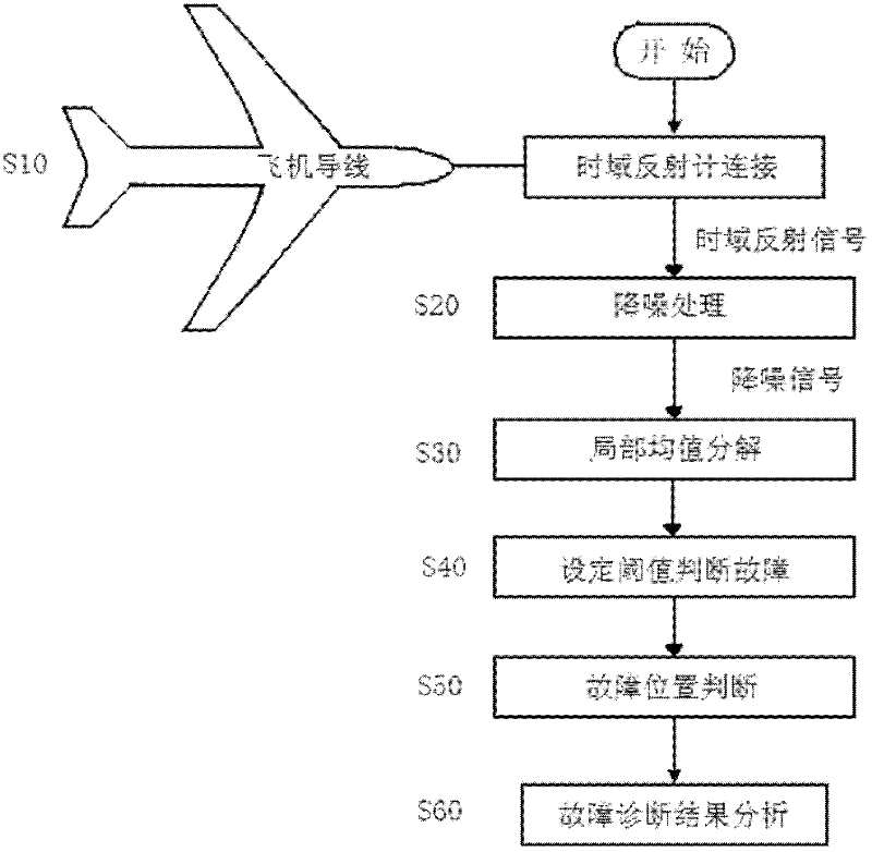
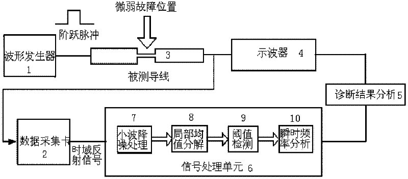
[0024] The invention uses local mean value decomposition to realize the weak fault diagnosis and location method of aircraft conductors. First, the time domain reflectometer is used to obtain the time domain reflection signal, and the reflection signal is subjected to noise reduction processing, so as to reduce noise interference and make the diagnosis result more accurate. After obtaining the noise-reduced time-domain reflection signal, use local mean decomposition to decompose any original non-stationary signal into the sum of several instantaneous frequency PF components with physical meaning, where each PF component consists of an envelope signal and a The envelope signal is the instantaneous amplitude of the PF component, and the instant...


PUM


Abstract

The invention provides a method for realizing weak fault diagnosis and location of an airplane wire by utilizing local mean decomposition. The method comprises the following steps of: connecting the airplane wire with a time domain reflectometer by an aviation plug; denoising the time domain reflected signal obtained by the time domain reflectometer from the tested wire; carrying out local mean decomposition on the denoised time domain reflected signal to obtain time frequency distribution of the time domain reflected signal; analyzing instantaneous frequency changes of the fault positions by utilizing the time frequency distribution, obtained after local mean decomposition, of the time domain reflected signal; analyzing instantaneous frequency changes of the wire with weak faults after diagnosis by utilizing the time frequency distribution, obtained after local mean decomposition, of the time domain reflected signal to obtain the positions of the weak faults in the wire; and comprehensively analyzing the weak fault diagnosis results of the airplane wire, and analyzing the detection speed and detecting the precision parameters. The method has the following beneficial effect that: the time domain reflectometer is utilized to detect the weak faults of the wire, so the weak fault detection rate is high and the weak fault false alarm rate is low.

Description

technical field [0001] The invention relates to a method for diagnosing and locating weak faults of aircraft wires. In particular, it relates to a method for diagnosing and locating weak faults of aircraft wires by using local mean value decomposition. Background technique [0002] Aircraft wires are important devices that provide power and control signals for aircraft electronic systems, and are widely distributed in various types of aircraft. With the growth of aircraft age, aircraft wires work in a complex environment for a long time, and are prone to failures such as insulation layer wear, aging, and corrosion, which eventually lead to short circuits and open circuits of aircraft wires, burying hidden dangers for aircraft safety. It can be seen that whether the aircraft wire can work well under normal working conditions will directly affect the safety of aircraft flight. Among the existing fault detection methods of aircraft wires, the time domain reflection detection ...

Claims


Application Information

Patent Timeline
IPC IPC(8): G01R31/11
Inventor 石旭东张璐荆涛聂冰亮刘承宗
Owner CIVIL AVIATION UNIV OF CHINA
Learn More