Diagnostic program, diagnostic method, and semiconductor device

a diagnostic program and memory technology, applied in the direction of redundant data error correction, instruments, digital storage, etc., can solve the problems of large circuit scale, large calculation delay, and new problems found by inventor, and achieve the effect of improving the failure detection rate of the address circuit of the memory

Inactive Publication Date: 2016-09-29
RENESAS ELECTRONICS CORP
View PDF4 Cites 6 Cited by
  • Summary
  • Abstract
  • Description
  • Claims
  • Application Information

AI Technical Summary

Benefits of technology

[0012]In a memory to which an ECC decoder is coupled, it is possible to improve a failure detection rate of an address circuit of the memory without using address information to generate redundant bits and without rewriting the memory.

Problems solved by technology

As a result, the inventors have found that there are new problems as described below.
Therefore, a calculation load required for the error determination and correction processing is heavy.
When the error determination and correction processing is performed by software, the number of execution cycles is large, and when dedicated hardware that performs such processing is provided, the circuit scale is large and calculation delay is also large.
Further, it is found that there is the following problem in capability to detect a failure of an address circuit.
On the other hand, it is found that the related art is effective as a countermeasure against the mis-selection but is not sufficient as a countermeasure against the non-selection and multiple selection and the related art is not necessarily an effective means.
However, during the March test, data in the memory needs to be rewritten, so that it is necessary to limit access to a memory area where the data is rewritten from another master module.
Because of the limitation to the access, it is not preferable to apply the March test to a customer application.

Method used


Image

  • Diagnostic program, diagnostic method, and semiconductor device
  • Diagnostic program, diagnostic method, and semiconductor device
  • Diagnostic program, diagnostic method, and semiconductor device

Examples


first embodiment

[0022]Read-out from a plurality of addresses sharing the same word line

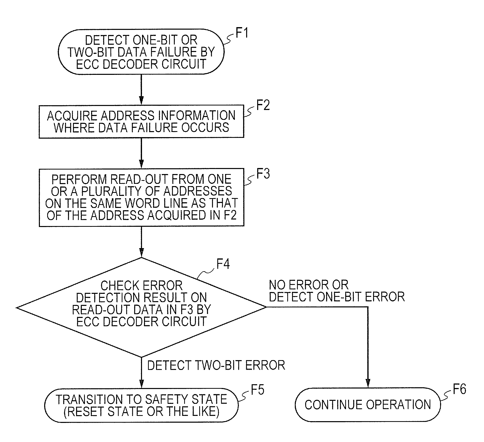
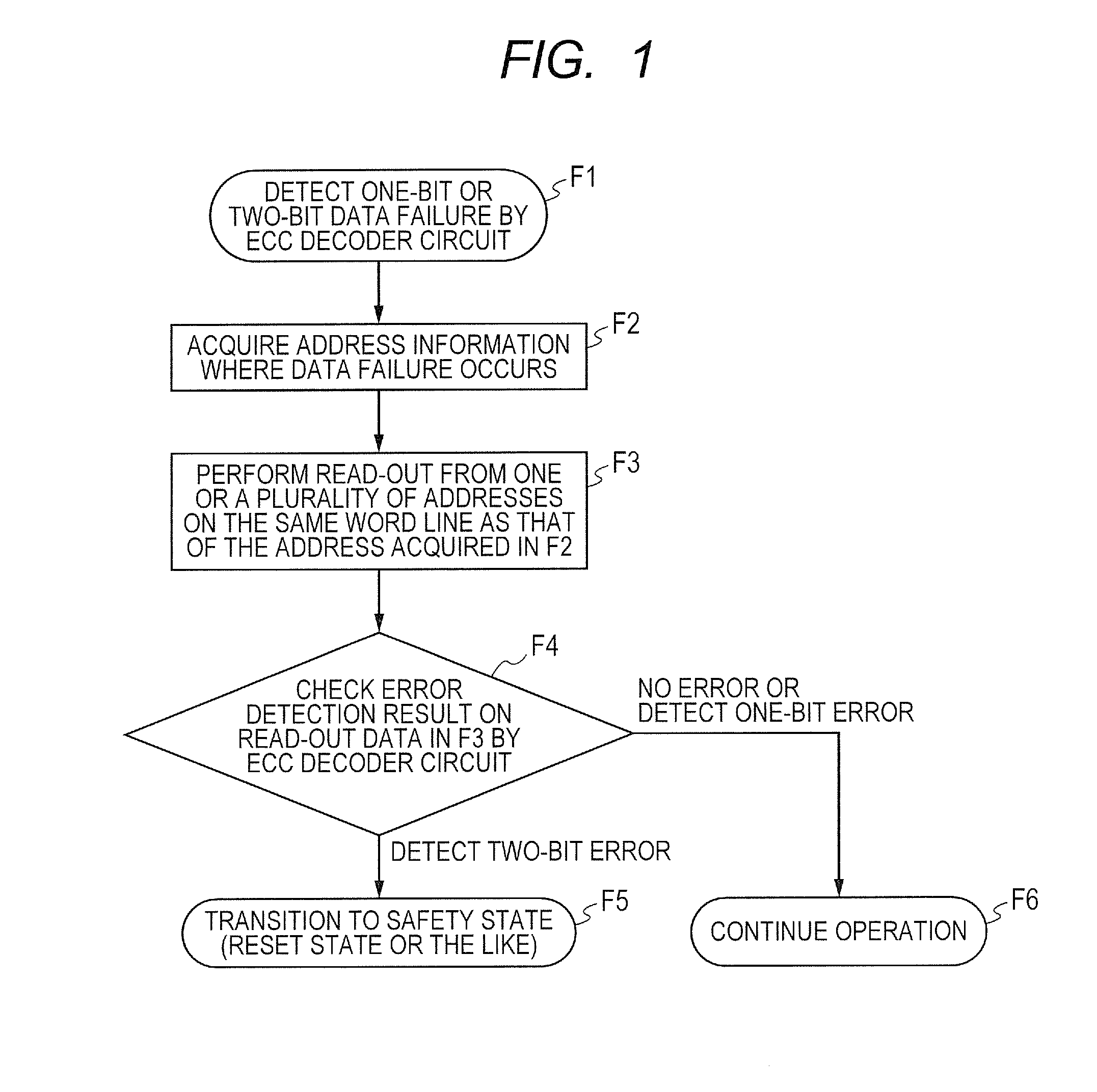
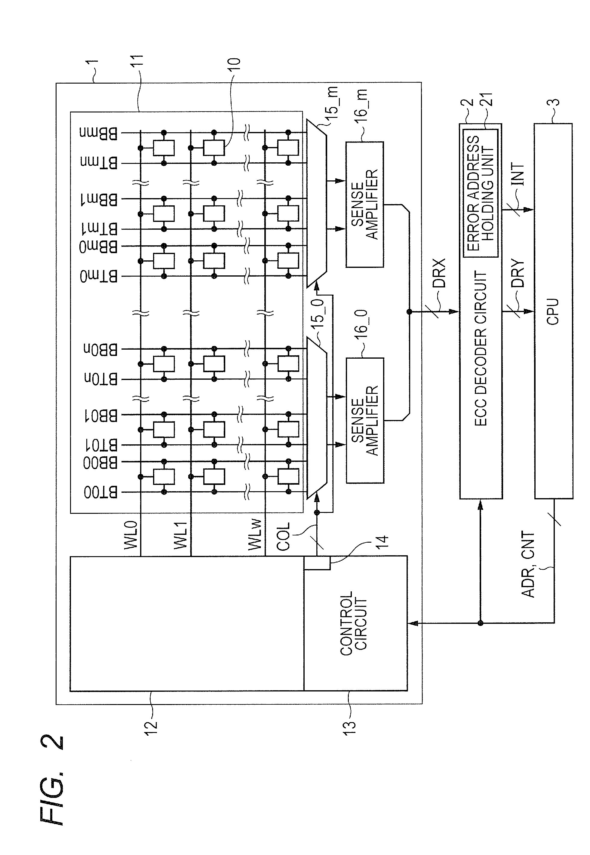
[0023]FIG. 1 is a flowchart showing a failure diagnosis flow of the first embodiment. FIG. 2 is a block diagram showing a configuration example of a memory which is an object of the failure diagnosis.

[0024]As shown in FIG. 2, a memory 1 which is an object of the failure diagnosis is coupled to an ECC decoder circuit 2 and a CPU (Central Processing Unit) 3. An address ADR and a control signal CNT are supplied from the CPU 3. Read-out data DRX which includes a data main body and redundant bits and which is read out from the memory 1 is inputted into the ECC decoder circuit 2. ECC-processed read-out data DRY and an interrupt signal INT that notifies of an error are outputted to the CPU 3. An error correction algorithm employed by the ECC decoder circuit 2 is, for example, SEC / DED. When there is no error in the read-out data DRX, the ECC decoder circuit 2 outputs a main body data part of the read-out data DRX to the ...

second embodiment

[0039]Read-Out from a Plurality of Addresses Sharing the Same Column Line

[0040]While the failure diagnosis flow focusing attention on the word line decoder circuit 12 is described in the first embodiment, the failure diagnosis flow focusing attention on the column line decoder circuit 14 will be described in the second embodiment.

[0041]FIG. 5 is a circuit diagram showing a configuration example of a column selector 15 of the memory 1 which is an object of the failure diagnosis. To facilitate understanding, only a part is shown in FIG. 5 and the other is omitted. Therefore, FIG. 5 shows a column selector 15_0 and a sense amplifier 16_0 for one bit, two bit line pairs BT00 / BB00 and BT01 / BB01 inputted from the memory mat 11, and two column lines COL0 and COL1 inputted from the column line decoder circuit 14.

[0042]The column selector 15_0 includes switch transistors MT00, MB00, MT01, and MB01 corresponding to inputted each bit line pair BT00 / BB00 and BT01 / BB01. The column lines COL0 and...

third embodiment

[0049]Read-Out from a Plurality of Addresses Sharing the Same Word Line or the Same Column Line

[0050]While the failure diagnosis flow is described which focuses attention on the word line decoder circuit 12 in the first embodiment and focuses attention on the column line decoder circuit 14 in the second embodiment, it is possible to combine these embodiments.

[0051]FIG. 7 is a flowchart showing a failure diagnosis flow of the third embodiment. In the same manner as in the first embodiment, following F2 of the failure diagnosis flow of the first embodiment shown in FIG. 1, F3 is performed to improve the failure detection rate of the word line decoder circuit 12, and further, in the same manner as in the second embodiment, F7 is performed to improve the failure detection rate of the column line decoder circuit 14. The other steps are the same as those in FIGS. 1 and 6, so that the description thereof will be omitted.

[0052]Thereby, it is possible to improve the failure detection rate of...


PUM


Abstract

In a memory with ECC, a failure detection rate of an address circuit of the memory is improved without using address information to generate redundant bits and without rewriting the memory.
The memory stores data of addresses different from each other and redundant bits added to the data in a plurality of memory cells sharing the same selection signal wiring (for example, a word line or a column line) and outputs read-out data corresponding to a specified address. An ECC decoder performs error detection on the read-out data. When an error is detected by the ECC decoder, a failure diagnosis of the memory is performed by accessing one or a plurality of addresses which are selected by the same selection signal wiring as selection signal wiring that selects read-out data where the error is detected and which are different from the address of the read-out data and evaluating a result of the error detection for the read-out data.

Description

CROSS-REFERENCE TO RELATED APPLICATIONS[0001]The disclosure of Japanese Patent Application No. 2015-062687 filed on Mar. 25, 2015 including the specification, drawings and abstract is incorporated herein by reference in its entirety.BACKGROUND[0002]The present invention relates to a diagnostic program and a diagnostic method for failure of memory and a semiconductor device where the memory is mounted. In particular, the present invention is preferably used for failure diagnosis of address circuit.RELATED ART[0003]In related art, as a countermeasure against a failure of memory, implementation of an ECC (Error Correction Code) circuit is widely known. For example, redundant bits generated by an error correction algorithm of SEC / DED (Single Error Correction / Double Error Detection) are added to data to be written and the data is written to a memory, it is determined whether there is no error or there is a one-bit error or a two-bit error from read-out main body data and redundant bits, ...

Claims


Application Information

Patent Timeline
Patent Type & Authority Applications(United States)
IPC IPC(8): G06F11/263G06F11/10G06F11/22
CPCG06F11/263G06F11/1076G06F11/2205G06F11/1016G11C11/417G11C29/52G11C2029/0411G06F11/1048G06F11/1068G06F12/0238G11C29/14G11C29/18G11C29/42
Inventor YAMATE, AKIHIROTAKI, YOSHITAKA
Owner RENESAS ELECTRONICS CORP
Why Eureka
Try Eureka