
Alternating current LED (Light Emitting Diode) driving circuit

A technology of LED drive and full-bridge rectifier circuit, which is applied in the direction of lamp circuit layout, electric light source, electrical components, etc., can solve the problem of low utilization rate of LED, and achieve the goal of increasing voltage input range, improving light efficiency, and enhancing applicability Effect

Inactive Publication Date: 2012-06-20
NINGBO BAISHI ELECTRIC
View PDF4 Cites 4 Cited by
  • Summary
  • Abstract
  • Description
  • Claims
  • Application Information

AI Technical Summary

Problems solved by technology

[0006] The problem to be solved by the present invention is to provide an AC LED drive circuit to overcome the defect of low LED utilization in the prior art AC LED drive circuit

Method used


Image

  • Alternating current LED (Light Emitting Diode) driving circuit
  • Alternating current LED (Light Emitting Diode) driving circuit
  • Alternating current LED (Light Emitting Diode) driving circuit

Examples


Embodiment 1

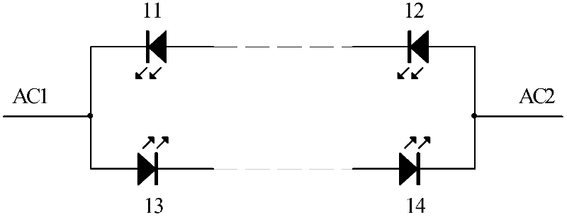
[0024] The circuit schematic diagram of an AC LED drive circuit according to the embodiment of the present invention is as follows: Figure 4 As shown, the circuit includes four rectifier diodes and k groups of LED units connected in parallel, where k is a natural number.

[0025] The four rectifier diodes comprise a first rectifier diode 41, a second rectifier diode 42, a third rectifier diode 43 and a fourth rectifier diode 44, and the four rectifier diodes form a full-bridge rectifier circuit, and the full-bridge rectifier circuit The two input ends are respectively connected to the two ends AC1 and AC2 of the AC input.

[0026] The LED unit is composed of n LEDs connected in series, where n is a natural number. The k groups of LED units connected in parallel include the first group of LED units, ..., the kth group of LED units, and the first group of LED units includes LED1_1, ..., LED1_n, ... ..., the kth group of LED units includes LEDk_1, ..., LEDk_n.

[0027] Taking...

Embodiment 2

[0030] The circuit schematic diagram of an AC LED drive circuit according to the embodiment of the present invention is as follows: Figure 5 As shown, the circuit includes four rectifying diodes, one constant current diode and k groups of LED units connected in parallel, where k is a natural number.

[0031] The four rectifier diodes include a first rectifier diode D1, a second rectifier diode D2, a third rectifier diode D3 and a fourth rectifier diode D4; the four rectifier diodes constitute a full-bridge rectifier circuit, and the full-bridge rectifier circuit The two input terminals are respectively connected to two ends of the AC input AC1 and AC2, the positive output terminal is connected to the positive common terminal of the k groups of LED units connected in parallel, and the negative output terminal is connected to the negative pole of the constant current diode.

[0032] The constant current diode is connected in series with the k groups of parallel-connected LED un...

Embodiment 3

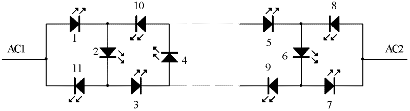
[0038] The circuit schematic diagram of an AC LED driving circuit according to the embodiment of the present invention is as follows: Image 6 As shown, the circuit includes four rectifier diodes and k groups of LED units connected in parallel, where k is a natural number.

[0039] The four rectifier diodes include a first rectifier diode D1, a second rectifier diode D2, a third rectifier diode D3 and a fourth rectifier diode D4, the four rectifier diodes constitute a full-bridge rectifier circuit, and the The two input terminals are respectively connected to the two ends AC1 and AC2 of the AC input.

[0040] The LED unit consists of n LEDs connected in series, where n is a natural number. The k groups of LED units connected in parallel include a first group of LED units, ..., a k-th group of LED units, and the first group of LED units includes LED1_1,..., LED1_n,... . . , the k-th group of LED units includes LEDk_1, . . . , LEDk_n.

[0041] In the k groups of LED units con...


PUM


Abstract

The invention discloses an alternating current LED (Light Emitting Diode) driving circuit which comprises four rectifier diodes, a constant current diode and k sets of LED units in parallel connection, wherein a full-bridge rectifier circuit is formed by the four rectifier diodes; AC1 and AC2 are bridge type rectification inputs; and a bridge type rectification output is a circuit which is formed by the constant current diode in serial connection with k parallel LED units composed of n serially connected LEDs. According to the alternating current LED driving circuit provided by the invention, four rectifier diodes and one constant current diode are used for driving an LED, so that the use ratio of the LED reaches 100%, the lighting effect is increased and the cost is lowered.

Description

technical field [0001] The invention relates to the technical field of LED driving, in particular to an AC LED driving circuit. Background technique [0002] At present, the driving circuit of AC LED generally adopts the following two methods: [0003] The driving circuit of the first LED is as follows figure 1 As shown, it includes two groups of LED units, each LED unit is composed of a plurality of LEDs in series, the two groups of LED units are connected in antiparallel, and the two common terminals thereof are respectively connected to the two input terminals of the AC power supply. Taking the waveform of the AC power supply as a sine wave as an example, the waveform of the AC power supply is as follows: figure 2 Shown, where t1 ~ t3 is a cycle of the waveform. use figure 1 In the LED driving circuit shown, during the period t1~t2, the current flows from the AC power supply AC1 terminal through LED13, ..., LED14 to the AC power supply AC2 terminal. At this time, LED...

Claims


Application Information

Patent Timeline
Patent Type & Authority Applications(China)
IPC IPC(8): H05B37/02
CPCH05B33/0809H05B37/02Y02B20/348H05B45/40Y02B20/30
Inventor 张利强
Owner NINGBO BAISHI ELECTRIC
Learn More