LED (light-emitting diode) multi-lamp distributed group drive system
A driving system and distributed technology, applied in the direction of lamp circuit layout, lighting devices, light sources, etc., can solve the problems of large number of elements in the flyback constant current drive circuit, poor EMI performance, low power factor, etc., and achieve simple structure, Effects of improved reliability and enhanced safety
- Summary
- Abstract
- Description
- Claims
- Application Information
AI Technical Summary
Problems solved by technology
Method used
Image

Examples
Embodiment 1
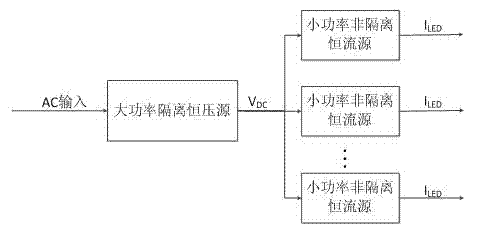
[0027] Embodiment one: see figure 2 , This high-efficiency LED multi-lamp distributed group drive system consists of a front-end high-power isolated constant voltage source and multiple rear-end low-power non-isolated constant current sources. The input terminal of the high-power isolated constant voltage source at the front end is connected to the AC mains, which is responsible for converting the AC mains into a set DC voltage and realizing constant voltage output through the power management chip. In addition, it is also responsible for the centralized electrical isolation of the entire system , EMI filtering, system protection and power factor correction. The input terminal of the low-power non-isolated constant current source at the rear end is connected to the output terminal of the high-power isolated constant voltage source at the front end, and the stable DC voltage output by the front end is converted into the required DC current through the constant current circuit ...
PUM
 Abstract
Description
Claims
Application Information