Super-large variable vibrating feeder

A vibrating feeder, variable technology, applied in vibrating conveyors, conveyors, transportation and packaging, etc., can solve the problems of high power consumption, slow feeding speed, heavy maintenance workload, etc., and achieve convenient adjustment of feeding volume , flexible angle adjustment and large adjustment range

Active Publication Date: 2012-06-27
鹤壁市煤化机械有限责任公司
View PDF5 Cites 1 Cited by
  • Summary
  • Abstract
  • Description
  • Claims
  • Application Information

AI Technical Summary

Problems solved by technology

The former is due to the reciprocating motion of the bottom plate of the coal feeder. When the bottom plate moves forward, the material does not move with the bottom plate due to the internal pressure and internal and external friction. Therefore, it is intermittent feeding, and the production efficiency is low. The maximum feeding amount per hour Hundreds of tons, high power consumption, serious wear of rotating parts, and heavy maintenance workload; and the latter, no matter what type of vibrating feeder, is to make the vibrating tank vibrate in simple harmonic, when the vibration acceleration component of the vibrating tank When it is greater than the component of the acceleration of gravity in the direction perpendicular to the bottom of the tank, the material in the tank is thrown up and jumps forward according to the parabolic trajectory to achieve the purpose of feeding. Because the material is jumping forward in this feeding method, there is a feeding speed Defects such as slowness, low productivity, the amount of feeding cannot be adjusted at any time, and a large amount of maintenance

Method used


Image

  • Super-large variable vibrating feeder
  • Super-large variable vibrating feeder
  • Super-large variable vibrating feeder

Examples


Embodiment Construction

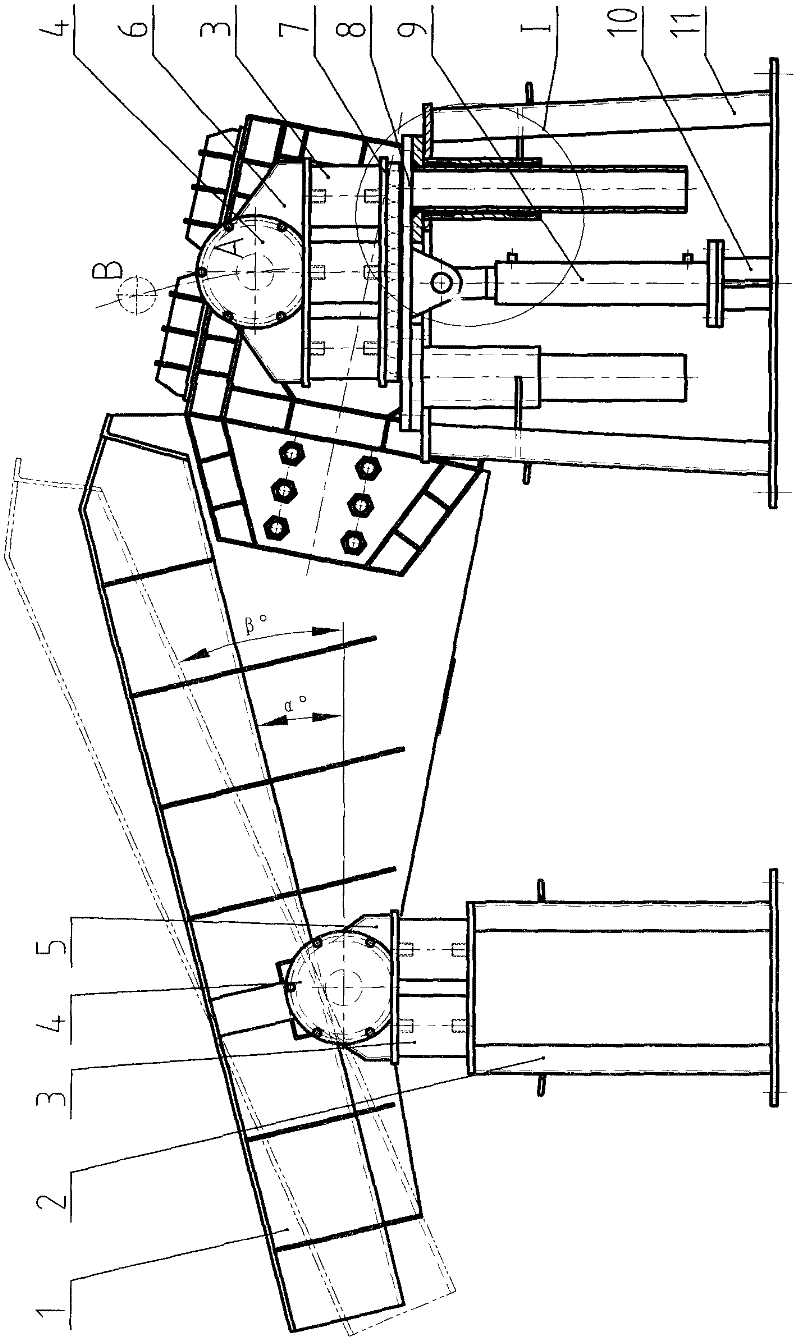
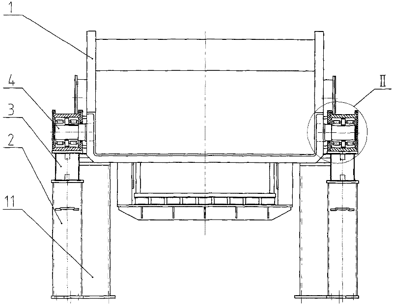
[0017] control Figure 1~4 , the super large variable vibrating feeder of the present invention consists of a vibrating feeder 1, a front support 2, a damping spring 3, a bearing body 4, a front pressing plate 5, a rear pressing plate 6, a displacement device 7, a lifting plate 8, an oil cylinder 9, Oil cylinder support 10 and rear support 11 constitute.

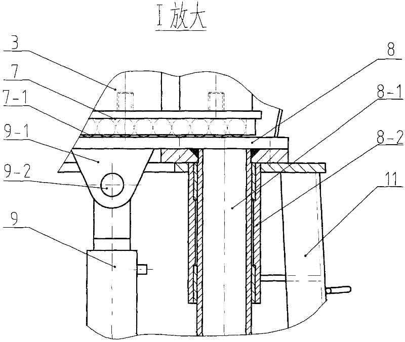
[0018] Its specific structural features are: the two sides of the front end of the vibrating feeder 1 are respectively equipped with the front support 2, the damping spring 3, the front pressure plate 5 and the bearing body 4, and the two sides of the rear end of the vibrating feeder 1 are respectively equipped with Bearing body 4 and rear pressure plate 6, the following of rear pressure plate 6 is connected with displacement device 7 by damping spring 3, and roller 7-1 is housed in displacement device 7, and the upper plane support roller 7-1 of lifting plate 8, its The lug 9-1 is welded below, and is connected with the up...


PUM


Abstract

The invention discloses a super-large variable vibrating feeder. A front support, an anti-vibrating spring, a front pressing plate and a bearing are mounted on each of two sides of the front end of the feeder, a bearing and a rear pressing plate are mounted on each of two sides of the rear end of the feeder, the lower surfaces of the rear pressing plates are connected with displacement devices through anti-vibrating springs, and oil cylinders and lifting plates are mounted on rear supports. When the feeding quantity needs to be adjusted, the lifting plates are pushed up by push rods of the oil cylinders, by the means, downward sliding force of materials in a trough of the feeder is greatly increased, and feeding of the materials is realized by means of resultant action of the downward sliding force and excitation force, so that super-large feeding quantity is realized. The super-large variable vibrating feeder is a breakthrough on production capacity, the feeding quantity can increase by 3-5 times on an original basis under the conditions that the size of a trough, power and excitation force of an original machine type are unchanged, the dip angle of a feeding trough body is wide in adjustment range and is freely adjustable within the range from -30 degrees to 0 degree, lifting of a hydraulic cylinder can be electrically controlled in real time, and real-time adjustment and long-range control of the feeding quantity are realized. The super-large variable vibrating feeder is mainly used for the fields of intermediate transfer and uniform feeding of various materials in various industries such as coal, metallurgy mines, chemical engineering, building materials and the like.

Description

Technical field: [0001] The present invention is a super-large variable vibrating feeder, which is mainly used in the fields of intermediate reloading and constant-speed feeding of various materials in various industries such as coal, metallurgical mines, chemical industry, and building materials. Background technique: [0002] At present, among the feeding equipment used in my country's coal, metallurgical and mining industries, the K-type reciprocating coal feeder was used the earliest, and various types of vibrating feeders were developed later, such as self-synchronized inertial vibrating feeders , Electromagnetic vibrating feeder, etc. The former is due to the reciprocating motion of the bottom plate of the coal feeder. When the bottom plate moves forward, the material does not move with the bottom plate due to the internal pressure and internal and external friction. Therefore, it is intermittent feeding, and the production efficiency is low. The maximum feeding amount ...

Claims


Application Information

Patent Timeline
Patent Type & Authority Applications(China)
IPC IPC(8): B65G27/04
Inventor 王运池桂建阁王学堂赵成群栗鹏伟
Owner 鹤壁市煤化机械有限责任公司
Why Eureka
Try Eureka