An automatic candle machine

A candle, automatic technology, applied in the field of candlesticks, can solve the problems of cost waste, easy to lose control of movement, and achieve the effect of saving power costs

Active Publication Date: 2021-07-02
温州铂芯电子科技有限公司
View PDF7 Cites 0 Cited by
  • Summary
  • Abstract
  • Description
  • Claims
  • Application Information

AI Technical Summary

Problems solved by technology

[0004] The object of the present invention is to provide an automatic candle machine to solve the above-mentioned background technology. In temples, electronic candles are generally used to replace candle holders, and they have the function of lifting. However, the lifting of existing electronic candles mainly uses electric push rods for lifting. , need to use multiple sets of drivers, resulting in waste of cost, and prone to loss of control when moving

Method used


Image

  • An automatic candle machine
  • An automatic candle machine
  • An automatic candle machine

Examples


Embodiment 1

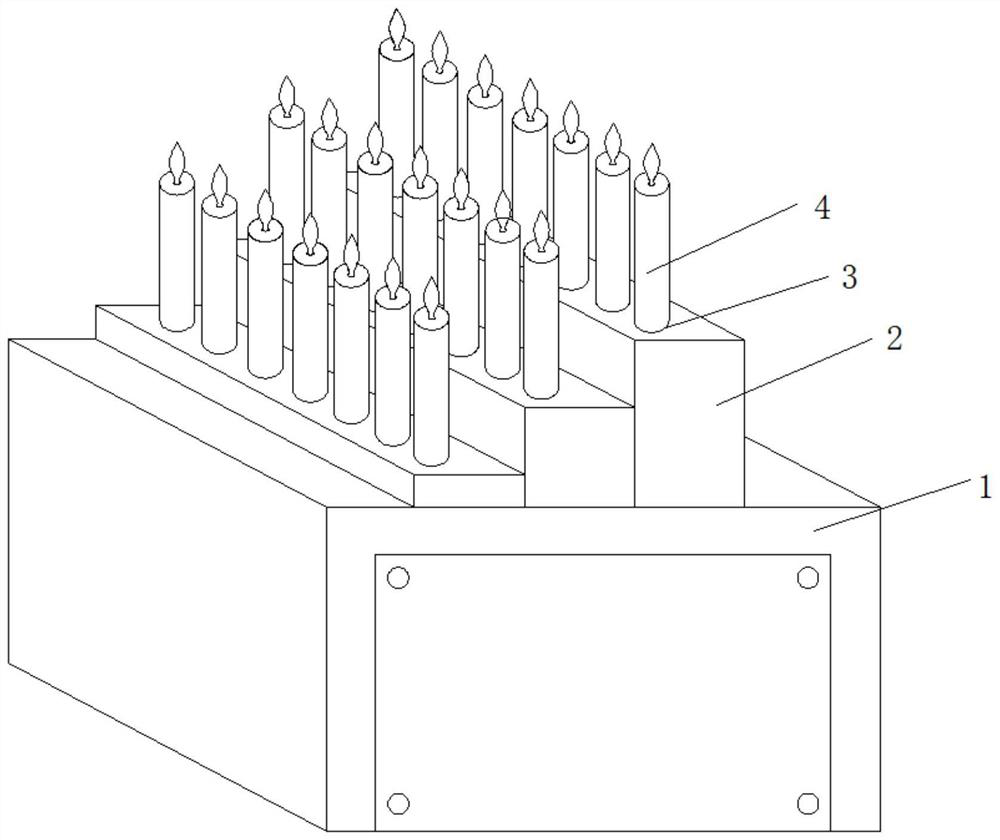
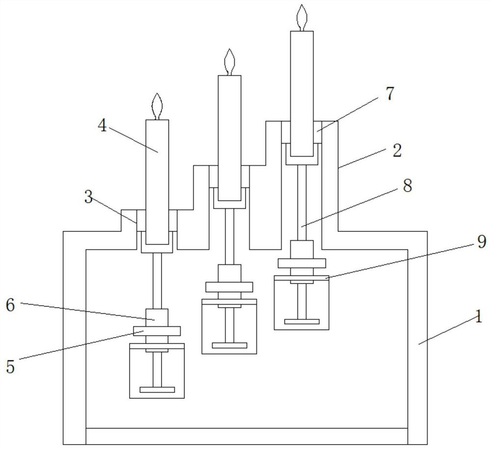
[0030] Such as Figure 1-5 As shown, the present invention provides a technical solution: an automatic candle machine, including a workbench 1, a candlestick frame 2 and an electric candle 4, the candlestick frame 2 is installed on the workbench 1, and the electric candle 4 is placed on the candlestick In the frame 2, multiple sets of the electric candles 4 are arranged side by side. The candlestick frame 2 is provided with a lifting hole 3, the electric candle 4 passes through the lifting hole 3, and the bottom end of the electric candle 4 is connected to the lifting mechanism. The top of the elevating mechanism is connected to the revolving platform 10, the bottom end of the electric candle 4 is sleeved in the revolving platform 10, the electric candle 4 is connected to the elevating mechanism through the revolving platform 10, and the elevating mechanism is located Inside the workbench 1 below the candlestick frame 2, a placement plate 9 is provided inside the workbench 1 a...

Embodiment 2

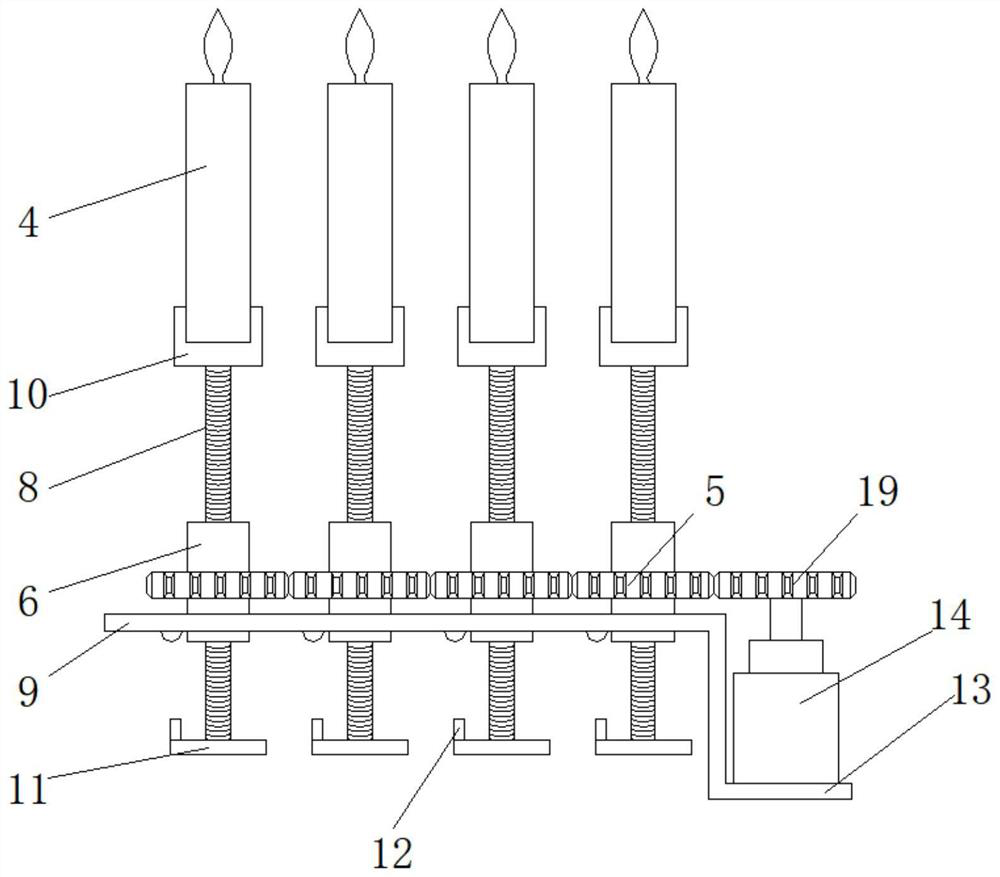
[0038] Such as figure 1 , figure 2 , Figure 4 , Figure 5 , Figure 6 , Figure 7 and Figure 8 As shown, the present invention provides a technical solution: an automatic candle machine, including a workbench 1, a candlestick frame 2 and an electric candle 4, the candlestick frame 2 is installed on the workbench 1, and the electric candle 4 is placed on the candlestick In the frame 2, multiple sets of the electric candles 4 are arranged side by side. The candlestick frame 2 is provided with a lifting hole 3, the electric candle 4 passes through the lifting hole 3, and the bottom end of the electric candle 4 is connected to the lifting mechanism. The top of the elevating mechanism is connected to the revolving platform 10, the bottom end of the electric candle 4 is sleeved in the revolving platform 10, the electric candle 4 is connected to the elevating mechanism through the revolving platform 10, and the elevating mechanism is located Inside the workbench 1 below the ...


PUM


Abstract

The invention discloses an automatic candle machine, which comprises a workbench, a candlestick frame and electric candles, the candlestick frame is installed on the workbench, the electric candles are placed in the candlestick frame, multiple groups of the electric candles are arranged side by side, the The candle holder is provided with a lifting hole, the electric candle passes through the lifting hole, the bottom end of the electric candle is connected to the lifting mechanism, the top of the lifting mechanism is connected to the spiral platform, and the bottom end of the electric candle is sleeved on the In the spiral table, the electric candle is connected with the lifting mechanism through the spiral table, and the lifting mechanism is placed inside the workbench below the candlestick frame. A protruding rod is set on the limit plate, and a motor switch is set on the placement plate where the lifting mechanism is installed. When the electric candle rises to the highest point, the protruding rod on the limit plate will press the motor switch, thereby cutting off the motor power. To achieve the purpose of stopping and avoid the uncontrolled rise of the automatic candle machine, automatic braking can be performed.

Description

technical field [0001] The invention relates to the technical field of candle holders, in particular to an automatic candle machine. Background technique [0002] Candle is a daily lighting tool, mainly made of paraffin. In ancient times, it was usually made of animal fat. It can burn and emit light. In addition, candles have a wide range of uses: they are also used in activities such as birthday parties, religious festivals, collective mourning, and weddings and funerals. In literary and artistic works, candles have a symbolic meaning of sacrifice and dedication. Because the candle will drop wax on the object when it is in use, and it is easy to produce harmful gas when the candle is used, so there is an electronic candle. The shape of the electronic candle is similar to that of an ordinary candle. role. [0003] Now in temples, candlesticks are generally replaced by electronic candles, which have the function of lifting, but the lifting of existing electronic candles m...

Claims


Application Information

Patent Timeline
Patent Type & Authority Patents(China)
IPC IPC(8): F21S10/04F21V21/36F21V23/04
CPCF21S10/04F21V21/36F21V23/04
Inventor 郑祥豹倪林安杨秀远温学存白洪武郑法艇
Owner 温州铂芯电子科技有限公司
Why Eureka
Try Eureka