Apparatus and methods for installing casing in a borehole

Inactive Publication Date: 2005-03-22
HALLIBURTON ENERGY SERVICES INC
View PDF26 Cites 11 Cited by
  • Summary
  • Abstract
  • Description
  • Claims
  • Application Information

AI Technical Summary

Benefits of technology

In another preferred embodiment, the casing string is used to supply the power fluid to the propulsion system so as to avoid the need for a power fluid coiled tubing. Further, a disposable propulsion system would be used whereby the propulsion system would be left downhole once the borehole has been completely drilled and the casing string installed. It should be appreciated that the propulsion system would be made inexpensively since it would not be retrieved. The engagement betwe

Problems solved by technology

This requires a large investment of resources and equipment and is very expensive.
Additionally, the hydrocarbons within the reservoir may be difficult to recover for several reasons.
For instance, the size and shape of the formation, the depth at which the hydrocarbons are located, and the location of the reservoir may make exploitation of the reservoir very difficult.
Further, drilling for oil and gas located under bodies of water, such as the North Sea, often presents greater difficulties.
Thus, the thickness of the coiled tubing is generally less than the drill pipe thickness used in rotary drilling, and the coiled tubing generally cannot withstand the same rotational and tension forces in comparison to the drill pipe used in rotary drilling.
However, there is very little clearance between the wheels of the propulsion system and the wall of the borehole and problems arise when the wheels encounter ridges or other variances in the dimensions of the wall of the borehole.
Further, at times there is an inadequate frictional engagement between the wheels and the wall of the borehole to adequately propel the propulsion system.
The advent in rece

Method used


Image

  • Apparatus and methods for installing casing in a borehole
  • Apparatus and methods for installing casing in a borehole
  • Apparatus and methods for installing casing in a borehole

Examples


Embodiment Construction

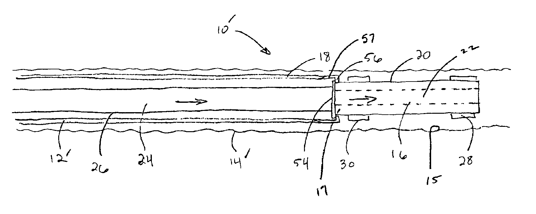
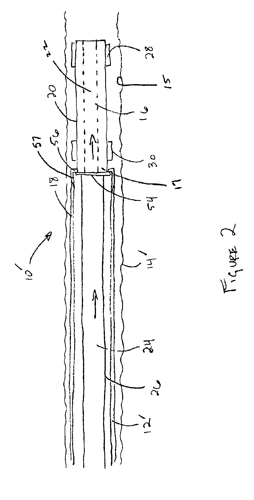
The preferred embodiments provide an improved method and apparatus for movement of equipment in passages. Specifically, the embodiments provide improved methods and apparatus for moving casing within a borehole.

One preferred embodiment includes an apparatus and method for moving casing into a borehole using a propulsion system. The propulsion system includes a housing comprising an upstream section with a traction module and a downstream section with a traction module. The traction modules are each connected to a ram mounted in a cylinder within one of the housing sections for propelling the housing up and down the borehole. In operation, one of the traction modules expands to engage the borehole wall ID, whether it be a cased or open borehole, while the hydraulic ram forces the housing downhole as the other traction module moves to the other end of its housing section in preparation for actuating its ram to move the housing farther downhole.

The propulsion system is not only capable...


PUM


Abstract

An apparatus and method of installing a casing string in a borehole, the apparatus comprising a propulsion system movable through the borehole; the propulsion system comprising an attachment member; and the attachment member being engagable with the casing string causing the casing string to move with the propulsion system through the borehole. The apparatus further including a conduit for circulating fluids through the propulsion system to provide the power to move the propulsion system. The propulsion system may also be disposable.

Description

CROSS-REFERENCE TO RELATED APPLICATIONSNot Applicable.STATEMENT REGARDING FEDERALLY SPONSORED RESEARCH OR DEVELOPMENTNot Applicable.BACKGROUND OF THE INVENTIONThe embodiments relate generally to methods and apparatus for movement of equipment in passages. More particularly, the embodiments relate to a propulsion system for pulling casing into boreholes.The art of drilling vertical, inclined, and horizontal boreholes plays an important role in the oil and gas industry. For example, a typical oil or gas well comprises a vertical borehole that is drilled by a rotary drill bit attached to the end of a drill string. The drill string is typically constructed of a series of connected links of drill pipe that extend between surface equipment and the drill bit. A drilling fluid, such as drilling mud, is pumped from the surface through the interior surface or flow channel of the drill string to the drill bit. The drilling fluid is used to cool and lubricate the drill bit, and remove debris an...

Claims


Application Information

Patent Timeline
IPC IPC(8): E21B23/00E21B23/04E21B43/02E21B43/10E21B23/08
CPCE21B23/04E21B43/10E21B23/08E21B2023/008E21B23/001
Inventor VIDRINE, WILLIAM L.GRIGSBY, TOMMYPHILLIPS, IAN
Owner HALLIBURTON ENERGY SERVICES INC
Why Eureka
Try Eureka