
Apparatus for producing water-in-oil emulsifield fuel and supplying the same

a technology of emulsified fuel and apparatus, which is applied in the direction of fuels, chemistry apparatus and processes, transportation and packaging, etc., can solve the problems of water and oil breakdown, severe limited heat source use efficiency, and water and oil phase stability breakdown, etc., to reduce fuel consumption, reduce excessive oxygen concentration, and save energy

Inactive Publication Date: 2006-07-06
PARK GIL WON
View PDF28 Cites 9 Cited by
  • Summary
  • Abstract
  • Description
  • Claims
  • Application Information

AI Technical Summary

Benefits of technology

[0008] The present invention has been made in an effort to solve these problems. It is an object of the present invention to provide an apparatus for producing and supplying water-in-oil emulsified fuel in which an emulsifier and water are mixed in crude oil such as bunker C oil (hereinafter ‘B-C oil’) or bunker A oil (hereinafter ‘B-A oil’) at an optimal ratio, and the resulting water-in-oil emulsified fuel is supplied to a boiler where full combustion takes place, thereby preventing contribution to air pollution and reducing energy requirements.
[0009] It is another object of the present invention to provide an apparatus for producing and supplying water-in-oil emulsified fuel in which a drive apparatus is simplified to thereby minimize areas of potential breakdown and provide for greater durability of the overall apparatus.
[0035] In the apparatus for producing and supplying water-in-oil emulsified fuel of the present invention, an emulsifier and water are primarily mixed in crude oil such as B-C oil or B-A oil, then an emulsified fuel, which has undergone a second mixing process that forms very minute water-in-oil particles, is maintained at a predetermined temperature in the emulsion tank. At the same tank, the emulsified fuel circulates through the circulation system of the emulsion tank to be supplied to the boiler while being maintained in an optimum emulsion state. As a result, a combustion is not discontinued, and fuel consumption is reduced.
[0036] Further, with the emulsified fuel supplied from the apparatus of the present invention, the fuel particles combusted in the combustion chamber are made into minute particles, that is, to particle sizes roughly 10,000 smaller than with conventional fuel such that the possibility of contact with oxygen during combustion is increased, thereby ensuring significantly greater full combustion and reducing excessive oxygen concentration in the exhaust gas. Therefore, energy is saved and boiler efficiency is increased.
[0037] In addition, with the use of the apparatus of the present invention, an air pollution reduction device such as dust collecting equipment is unneeded, and overall equipment operation costs such as power costs and maintenance are reduced.

Problems solved by technology

In particular, water-in-oil (W / O) emulsified fuel is realized by mixing water or waste water, and a surface active agent (an emulsifier) in a high carbide, high viscosity oil such as crude oil (bunker C oil), which is a low cost, highly efficient heat source that is severely limited in use because it contributes to air pollution.
However, in the processes of storing, transporting, pre-heating, and performing burner supply, as a result of the differences in specific gravity and surface tension between the fuel oil and water, there is a breakdown in phase stability, separation between the water and oil, and fuel oil is supplied continuously in a non-uniform manner through a system of imprecise and unstable injection amount and injection ratio of water and oil.
Therefore, in the combustion process, stoppage of combustion repeatedly occurs and combustion efficiency is unfavorable such that it is difficult to obtain the goal for reducing fuel oil.

Method used


Image

  • Apparatus for producing water-in-oil emulsifield fuel and supplying the same
  • Apparatus for producing water-in-oil emulsifield fuel and supplying the same
  • Apparatus for producing water-in-oil emulsifield fuel and supplying the same

Examples


first embodiment

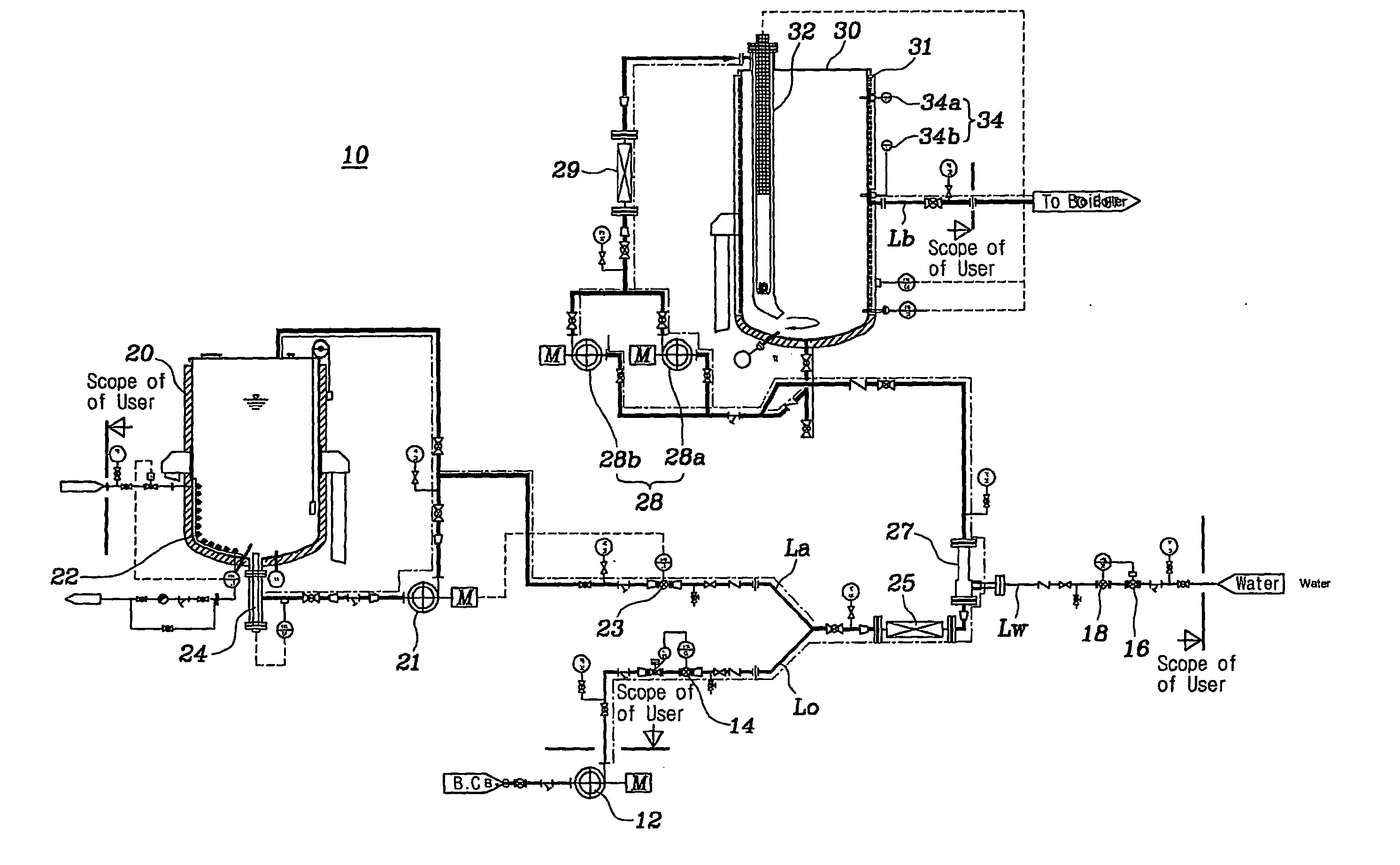
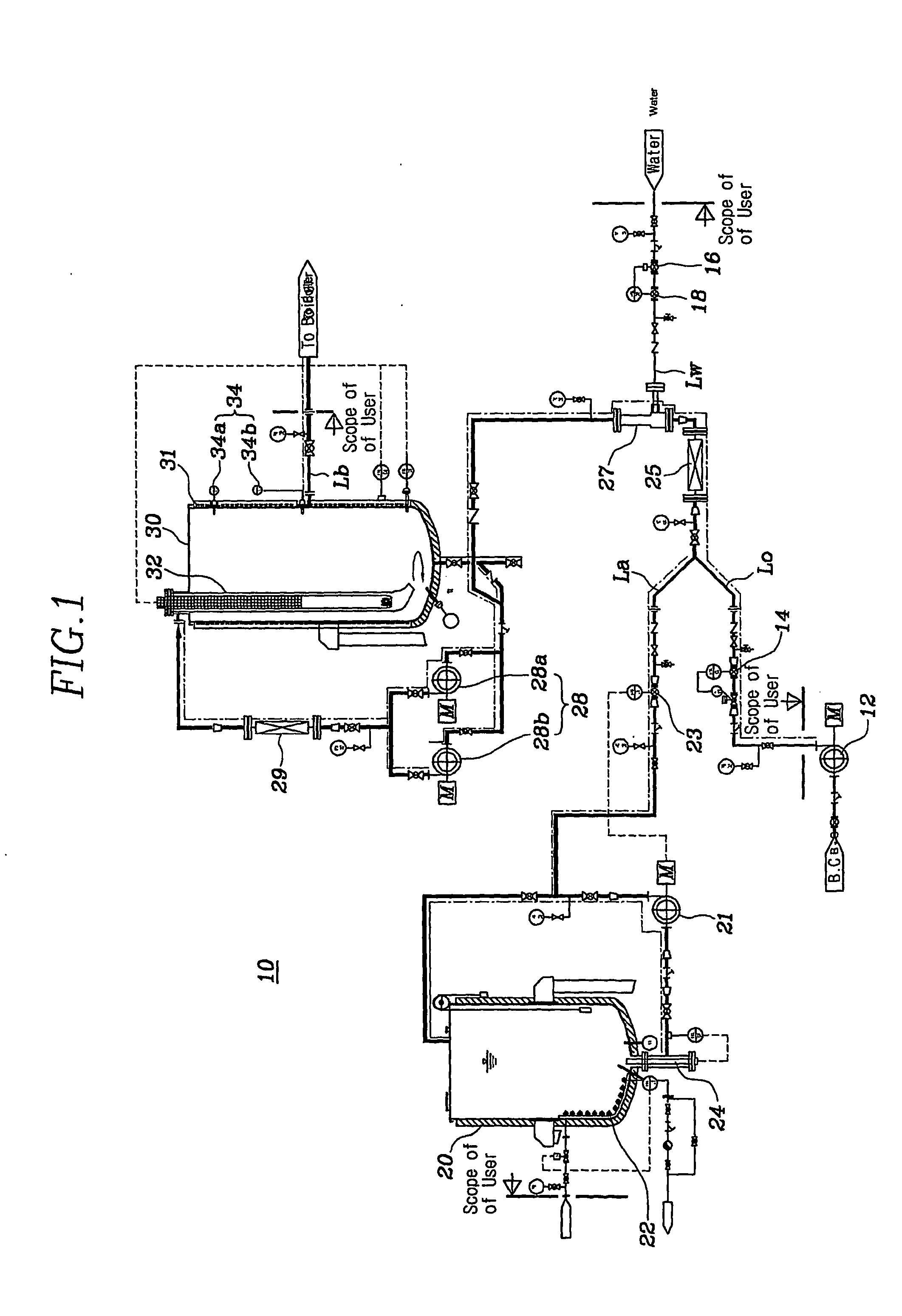
[0046]FIG. 1 is a structural view of an apparatus for producing and supplying water-in-oil emulsified fuel according to the present invention.

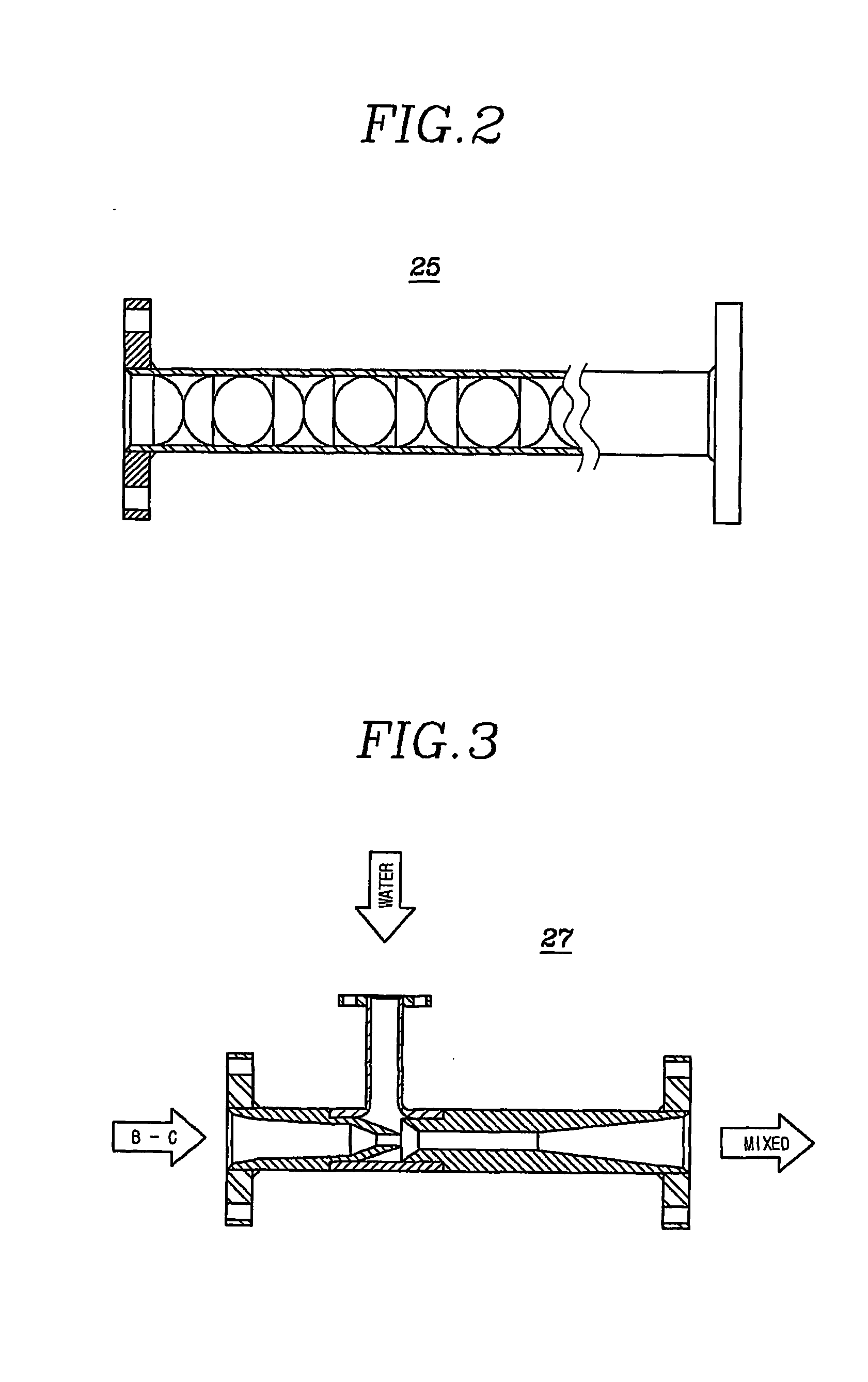
[0047] With reference to FIG. 1, an apparatus 10 for producing and supplying water-in-oil emulsified fuel includes an additive storage tank 20 for storing an emulsifier; an emulsion tank 30 for storing water-in-oil emulsified fuel; a raw material supplier for supplying at a predetermined ratio and according to predetermined values B-C oil, an emulsifier, and water, which become the raw materials for water-in-oil emulsified fuel; a first mixing section for consecutively and uniformly mixing the supplied raw materials; and a second mixing section for mixing the primarily mixed raw material oil with pre-emulsified fuel to perform emulsion.

[0048] The emulsifier stored in the additive storage tank 20 is an additive that acts to prevent the separation of water and oil when a high temperature state of the water-in-oil emulsified fuel is maintained. ...

second embodiment

[0081]FIG. 5 is a structural view of an apparatus for producing and supplying water-in-oil emulsified fuel according to the present invention.

[0082] With reference to FIG. 5, an apparatus 40 for producing and supplying water-in-oil emulsified fuel includes an additive storage tank 41 for storing an emulsifier; an emulsion tank 43 for storing water-in-oil emulsified fuel; a raw material supplier for supplying at a predetermined ratio and according to predetermined values B-C oil, an emulsifier, and water, which become the raw materials for water-in-oil emulsified fuel; a first mixing section for consecutively and uniformly mixing the supplied raw materials; and a second mixing section for mixing the primarily mixed raw material oil with pre-emulsified fuel to perform emulsion. The apparatus also includes a service tank 45 that stores water-in-oil emulsified fuel before the same is supplied to a boiler.

[0083] It is preferable that the emulsion tank 43 is manufactured having a capacit...

third embodiment

[0088]FIG. 6 is a structural view of an apparatus for producing and supplying water-in-oil emulsified fuel according to the present invention.

[0089] With reference to FIG. 6, an apparatus 60 for producing and supplying water-in-oil emulsified fuel includes an additive storage tank 61 for storing an emulsifier; an emulsion tank 63 for storing water-in-oil emulsified fuel; a raw material supplier for supplying at a predetermined ratio and according to predetermined values B-C oil, an emulsifier, and water, which become the raw materials for water-in-oil emulsified fuel; a first mixing section for consecutively and uniformly mixing the supplied raw materials; and a second mixing section for mixing the primarily mixed raw material oil with pre-emulsified fuel to perform emulsion.

[0090] In the apparatus 60 for producing and supplying water-in-oil emulsified fuel according to the third embodiment, a circulation electric heater 70 and a third mixer 69 are mounted in this sequence on a cir...


PUM

PropertyMeasurementUnit
temperatureaaaaaaaaaa

Abstract

The present invention relates to an apparatus for producing and supplying water-in-oil emulsified fuel that supplies to a boiler water-in-oil emulsified fuel, which is emulsified by mixing an emulsifier and water in crude oil such as bunker C oil or bunker A oil. The apparatus for producing and supplying water-in-oil emulsified fuel includes an additive storage tank for storing an emulsifier; an emulsion tank for storing water-in-oil emulsified; a raw material supplier for supplying at a predetermined ratio and according to predetermined values B-C oil, an emulsifier, and water, which become the raw materials for water-in-oil emulsified fuel; a first mixing section for consecutively and uniformly mixing the supplied raw materials; and a second mixing section for mixing the primarily mixed raw material oil with pre-emulsified fuel to perform emulsion. The second mixing section is realized through a circulation system that includes an emulsion tank, a mixer pump, and a double mixer. Following the supply of a predetermined amount of the raw materials, emulsified fuel mixed in the circulation system is continuously circulated even if raw material supply is stopped such that emulsified fuel that is always in a uniform state is supplied while maintaining a predetermined ratio, a predetermined moisture particle state, and a predetermined temperature.

Description

BACKGROUND OF THE INVENTION [0001] (a) Field of the Invention [0002] The present invention relates to an apparatus for producing emulsified fuel and supplying the same to a boiler, and more particularly, to an apparatus for producing and supplying water-in-oil emulsified fuel that supplies to a boiler water-in-oil emulsified fuel, which is emulsified by mixing an emulsifier and water in crude oil such as bunker C oil or bunker A oil. [0003] (b) Description of the Related Art [0004] Generally, emulsion refers to the state of uniform dispersion to a minute particle state of a liquid that is within a liquid and unmixed with the same. [0005] In particular, water-in-oil (W / O) emulsified fuel is realized by mixing water or waste water, and a surface active agent (an emulsifier) in a high carbide, high viscosity oil such as crude oil (bunker C oil), which is a low cost, highly efficient heat source that is severely limited in use because it contributes to air pollution. Water-in-oil emulsi...

Claims


Application Information

Patent Timeline
Patent Type & Authority Applications(United States)
IPC IPC(8): C10L5/00
CPCB01F3/0807B01F3/0853B01F3/0861B01F3/088B01F5/0413B01F5/043B01F5/0615B01F5/0646B01F5/102B01F13/103B01F23/45B01F23/43B01F23/49B01F23/41B01F25/31243B01F25/312B01F25/43141B01F25/433B01F25/51B01F33/8212
Inventor HWANG, SUK-HA
Owner PARK GIL WON
Learn More