Prefabricated steel highway bridge

A prefabricated, highway technology, applied in the direction of bridges, truss bridges, bridge parts, etc., can solve the problems of small design bearing capacity, small installation space, narrow use range, etc., to reduce erection costs, increase width, and vehicle traffic capacity. improved effect

Inactive Publication Date: 2012-06-27
HENAN PROVINCIAL COMM PLANNING & DESIGN INST CO LTD
View PDF11 Cites 5 Cited by
  • Summary
  • Abstract
  • Description
  • Claims
  • Application Information

AI Technical Summary

Problems solved by technology

Because the height of the supporting beam is limited by the installation space, it is difficult to install the beam and the design bearing capacity is small. Under normal circumstances, the allowable clear width of the steel bridge deck is only 3.7 meters. The narrow deck width results in insufficient vehicle traffic capacity. In the event of disasters or other emergencies, emergency rescue vehicles or large transport vehicles with special equipment cannot pass smoothly
[0003] Chinese utility model patent (Patent No.: 201120030406.6) discloses a "truss of assembled steel bridge", which solves the problem of small installation space for the traditional assembled highway steel bridge beam, but has the following shortcomings in practical application: 1. Some steel trusses of traditional structure cannot be used directly, and steel trusses must be remade, which increases the production and use costs of highway steel bridges; 2. There are no corresponding matching beams and fixed connection devices between beams and steel trusses, It needs to be designed separately when used; 3. The scope of use is narrow and not universal

Method used


Image

  • Prefabricated steel highway bridge
  • Prefabricated steel highway bridge
  • Prefabricated steel highway bridge

Examples


Embodiment Construction

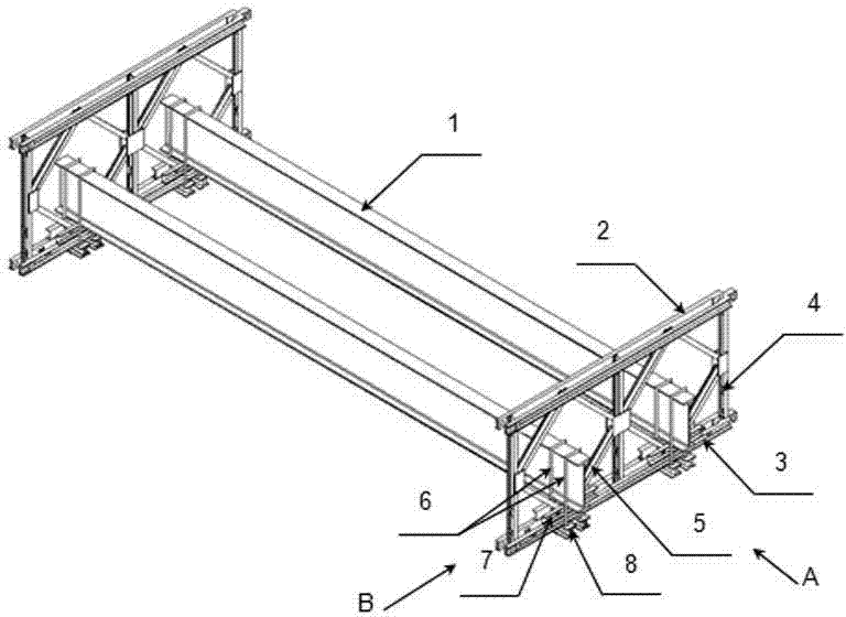
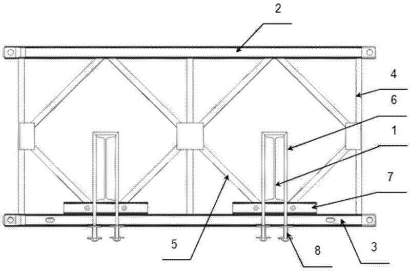
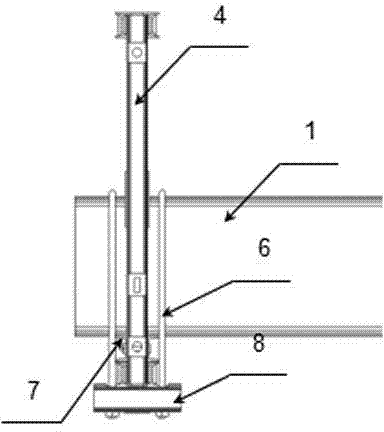
[0013] Such as figure 1 , 2 , 3, the assembled highway steel bridge of the present invention comprises a steel truss and a large crossbeam 1 erected between the steel trusses, the steel truss includes an upper chord 2, a lower chord 3 and an interval between the upper chord 2 and the lower chord The vertical rods 4 between the rods 3, the rectangular frame composed of two adjacent vertical rods 4 and the upper chord 2 and the lower chord 3 are composed of four oblique rods 5 respectively fixed at the center of the upper and lower chords and vertical rods. Diamond-shaped support frame, a pair of channel steel 7 with opposite openings is arranged on the lower chord 3 at the bottom of the diamond-shaped support frame. A support plane is formed between the root slanting bars 5, and the large beam 1 is horizontally placed on the support plane; two U-shaped bolts 6 with downward openings arranged on both sides of the lower chord 3 connect the large beam 1, the channel steel 7 and t...


PUM


Abstract

The invention discloses a prefabricated steel highway bridge, which comprises steel trusses and a big beam mounted between the steel trusses. The steel truss comprises an upper chord member, a lower chord member, and vertical bars supporting between the upper chord member and the lower chord member in a spaced manner. A rhombic supporting frame is arranged inside a rectangular frame which consists of the two adjacent vertical bars, the upper chord member and the lower chord member, wherein the rhombic supporting frame consists of four sloped bars respectively fixed at the centers of the upper and lower chord members and the vertical bars. A clamping member for internally clamping two adjacent sloped bars through fastening bolts and forming a supporting plane between the two sloped bars is arranged on the lower chord member at the bottom of the rhombic supporting frame, and the big beam is horizontally placed on the supporting plane. Two U-shaped bolts with downwardly oriented openings are arranged on two sides of the lower chord member so that the big beam, the clamping member and the lower chord member are connected together, and a connector for connecting the two U-shaped bolts together is arranged at the bottom of the lower chord member. The invention has the following advantages: a smart fixing manner is designed based on a steel truss of a traditional structure so that the prefabricated steel highway bridge floor is widened.

Description

technical field [0001] The invention relates to an assembled highway steel bridge, in particular to an assembled highway steel bridge with a large beam bearing capacity. Background technique [0002] The prefabricated highway steel bridge is a common temporary bridge facility. It is not limited by the bridge type. The standardized girders can be constructed in parallel at multiple points. It has the characteristics of light weight, large bearing capacity and fast construction speed. The beam of the traditional prefabricated highway steel bridge is erected between the vertical bars and oblique bars of the trusses on both sides, and the beam and the truss are connected together by positioning pins. As the height of the supporting beam is limited by the installation space, it is difficult to install the beam and the design bearing capacity is small. Under normal circumstances, the allowable clear width of the bridge deck of the steel bridge is only 3.7 meters. The narrow deck w...

Claims


Application Information

Patent Timeline
Patent Type & Authority Applications(China)
IPC IPC(8): E01D6/00E01D19/00
Inventor 常兴文王丽刘东旭李斐然张晓炜郭金山王智勇曾勇
Owner HENAN PROVINCIAL COMM PLANNING & DESIGN INST CO LTD
Why Eureka
Try Eureka