Anticollision remote control parking spot lock

A parking lock and anti-collision technology, which is applied in the field of parking locks, can solve the problems of easily damaged car body, easily damaged parking locks, outdated shapes and styles, etc., and achieves the effect of ensuring durability, saving power consumption and having a simple structure.

Inactive Publication Date: 2012-06-27
TIANJIN CHULIAN TECH DEV
View PDF5 Cites 3 Cited by
  • Summary
  • Abstract
  • Description
  • Claims
  • Application Information

AI Technical Summary

Problems solved by technology

[0002] At present, as more and more people buy cars, special parking spaces are also increasing. In order to avoid unpleasant situations such as quarrels and other unpleasant situations due to others intentionally or unintentionally occupying their parking spaces, users of parking spaces usually set up a parking space at the parking space. Parking locks, most of the existing parking locks on the market are mechanical and manual. When the car enters or exits the parking space, you need to get off the car to prop up or put down the pole of the parking lock, and then lock it. It is very inconvenient to use. When it comes to inclement weather such as rain or snow, it is even more troublesome
In addition, the existing mechanical and manual parking locks basically have no anti-collision function. Once a passing vehicle accidentally hits the parking lock, not only the car body is easily damaged, but the parking lock is also easily damaged. Parking locks damaged by collisions are not easy to replace and maintain; secondly, the appearance and style are relatively old, lack aesthetic feeling, and rough workmanship, which does not conform to the aesthetics of modern people, and is far from meeting people's individual needs for parking locks.

Method used


Image

  • Anticollision remote control parking spot lock
  • Anticollision remote control parking spot lock
  • Anticollision remote control parking spot lock

Examples


Embodiment Construction

[0027] The present invention will be further described in detail below in conjunction with specific embodiments.

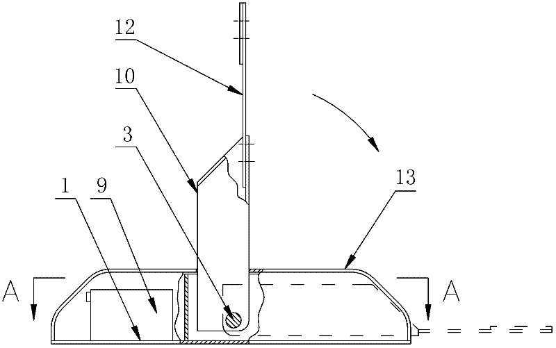
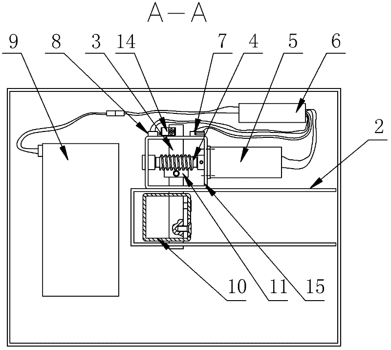
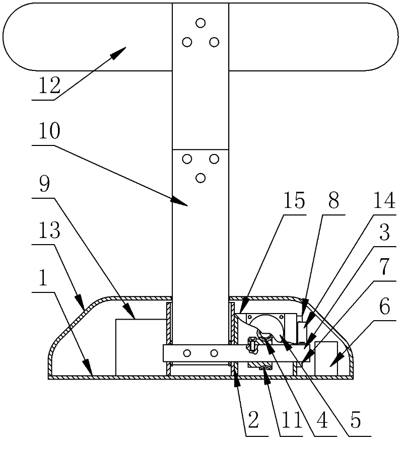
[0028] Such as Figure 1 to 3 As shown, the anti-collision remote control parking lock of the present invention mainly includes two parts: mechanical and remote control. The mechanical part includes a bottom plate 1. A U-shaped bracket 2 and a □-shaped bracket 15 are fixed on the bottom plate 1. A side wall on the bracket 2 is adjacent to a side wall of the □-shaped bracket 15, a support tube 10 is inserted between the two opposite side walls of the U-shaped bracket 2, and the bottom end of the support tube 10 It is connected to the U-shaped bracket 2 by a rotating pin 3, the rotating pin 3 and the support tube 10 are fixed by fasteners, and the upper end of the support tube 10 is fixed to an anti-collision plate 12. The anti-collision plate 12 is an elastic steel plate; one end of the rotating pin 3 penetrates the U-shaped bracket 2 and the □-shaped bracket 15 and ...


PUM


Abstract

The invention discloses an anticollision remote control parking spot lock which comprises a bottom plate and a direct current motor positive and negative rotation wireless remote control device, wherein a U-shaped bracket and a square bracket are fixed on the bottom plate; one side wall of the U-shaped bracket is next to one side wall of the square bracket; a supporting pipe is inserted between two opposite side walls of the U-shaped bracket; the bottom end of the supporting pipe is connected with the U-shaped bracket through a rotating hinge pin; the upper end of the supporting pipe is fixedly connected with an elastic anticollision plate; one end of the rotating hinge pin runs through the U-shaped bracket and the square bracket to form a cantilever shaft section; a wafer is fixed on the cantilever shaft section through a jack screw; a direct current motor is arranged outside the square bracket; the output end of the direct current motor is connected with a worm supported in the square bracket; and a worm gear meshed with the worm is fixedly connected on a shaft section on the rotating hinge pin, which is positioned in the square bracket. The anticollision remote control parking spot lock has simple structure, is convenient to operate and has an anticollision function. A user can realize random parking of a vehicle without going out of the vehicle.

Description

Technical field [0001] The invention relates to a parking space lock, in particular to a parking space lock with anti-collision function and remote control. Background technique [0002] At present, with more and more people buying cars, dedicated parking spaces are also increasing. In order to avoid unpleasant situations such as quarrels due to other people's intentional or unintentional occupation of their own parking spaces, users of parking spaces usually set up a parking space. Parking locks. Most of the existing parking locks on the market are mechanical and manual. When the car enters and exits the parking space, you need to get off the car to prop up or lower the support pole of the parking space lock, and then lock it. It is very inconvenient to use. When it comes to severe weather such as rain or snow, it becomes more troublesome. In addition, the existing mechanical manual parking locks basically have no anti-collision function. If nearby passing vehicles are accident...

Claims


Application Information

Patent Timeline
Patent Type & Authority Applications(China)
IPC IPC(8): E04H6/42G08C17/02
Inventor 王诗军王明月
Owner TIANJIN CHULIAN TECH DEV
Why Eureka
Try Eureka