Gas passage and combustion chamber structure of three-valve engine

A combustion chamber and engine technology, used in engine components, combustion engines, machines/engines, etc., can solve the problems of low flame propagation speed, low air intake flow coefficient, and large heat transfer area, and achieve fast flame propagation speed and high heat transfer. High air flow coefficient and the effect of reducing valve noise

Inactive Publication Date: 2012-06-27
力帆科技(集团)股份有限公司
View PDF6 Cites 3 Cited by
  • Summary
  • Abstract
  • Description
  • Claims
  • Application Information

AI Technical Summary

Problems solved by technology

The shape of the combustion chamber of the conventional three-valve engine is irregular, there are many steps in the combustion chamber, the air flow resistance is large, the flame propagation speed is low, and the heat transfer area is large, the heat loss is large, resulting in low thermal efficiency
At the same time, the unreasonable design of the intake and exhaust passages of the three-valve engine will lead to low intake flow coefficient, small intake tumble flow, and insufficient intake air, so that the movement speed of the mixed gas flow is slow; similarly, the exhaust flow coefficient Smaller, insufficient exhaust so the engine can't draw in as much fuel mixture
The above factors will affect the greater power output of the engine on the one hand, and on the other hand, will increase the energy consumption of the engine
Chinese patent ZL02113222.4 disclosed a three-valve engine combustion chamber on July 21, 2004. The combustion chamber is composed of a canopy and a spherical surface. Although it has the characteristics of simple manufacture, the power and torque are small, and the power is 5.6kw / 8500r / min, the torque is 7.2N.m / 6500r / min, and the noise of the valve is relatively large

Method used


Image

  • Gas passage and combustion chamber structure of three-valve engine
  • Gas passage and combustion chamber structure of three-valve engine
  • Gas passage and combustion chamber structure of three-valve engine

Examples


Embodiment Construction

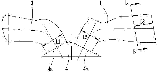
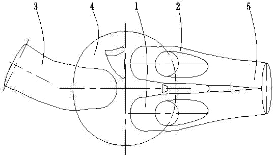
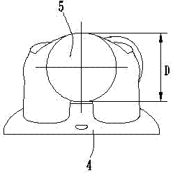
[0012] The present invention will be further described below in conjunction with drawings and embodiments.

[0013] Such as figure 1 , figure 2 , image 3 As shown, the cylinder head of the three-valve engine is provided with a first intake port 1, a second intake port 2, an exhaust port 3 and a combustion chamber 4. Wherein, the lower end of the combustion chamber 4 is open, and the outline of the lower port of the combustion chamber 4 is approximately circular. The inner top wall of the combustion chamber 4 is a double-slope structure, such as figure 1 The one shown on the left is the first slope 4a, the one on the right is the second slope 4b, and the deepest depth of the combustion chamber 4 is 9-13mm. The first slope 4a and the second slope 4b have a smooth transition through a curved surface, and there is an included angle of 120-128° between the first slope 4a and the second slope 4b. In this embodiment, the first slope 4a and the second slope The angle between th...


PUM


Abstract

The invention discloses a gas passage and combustion chamber structure of a three-valve engine. The inner roof wall of a combustion chamber (4) has a double-bevel structure, the included angle ranging from 120 degrees to 128 degrees is formed between a first bevel (4a) and a second bevel (4b), and an inlet end of a first gas inlet passage (1) and an inlet end of a second gas inlet passage (2) areconverged into a gas inlet passage section (5) with outer end orifice circular and inner end orifice elliptical. An inlet section of a gas exhaust passage (3) is a straight section with the diameter (L1) ranging from 17mm to 21mm, and outlet sections of the first gas inlet passage (1) and the second gas inlet passage (2) are also straight sections with the diameter (L2) ranging from 14mm to 18mm.After the gas inlet passages and the gas exhaust passage are optimized, the three-valve engine can realize gas feeding and exhausting more sufficiently and has higher combustion efficiency, and meanwhile, heat loss can be reduced and heat efficiency can be increased effectively.

Description

technical field [0001] The invention belongs to the technical field of engines, and in particular relates to the structure of an air channel and a combustion chamber of a three-valve engine. Background technique [0002] At present, small-displacement motorcycle engines all adopt a double-valve structure. This is because small-displacement motorcycle engines have relatively low performance requirements for medium and high speeds. Although the conventional double-valve engine is relatively noisy, it can meet the operating requirements. Require. With the continuous improvement of performance requirements, it has become a development trend to use three-valve engines on small-displacement motorcycles. The shape of the combustion chamber of the conventional three-valve engine is irregular, there are many steps in the combustion chamber, the airflow resistance is large, the flame propagation speed is low, and the heat transfer area is large, and the heat loss is large, resulting ...

Claims


Application Information

Patent Timeline
Patent Type & Authority Applications(China)
IPC IPC(8): F02B23/00F02F1/42F02M35/104F01N13/08
CPCY02T10/125Y02T10/12
Inventor 廖寿昌陈微微罗园
Owner 力帆科技(集团)股份有限公司
Why Eureka
Try Eureka