Transmission structure of oil pump

A technology of transmission structure and oil pump, which is applied in the direction of machine/engine, pressure lubrication of lubricating pump, mechanical equipment, etc., can solve the problems of difficult layout and increased cost, and achieve convenient disassembly and maintenance, reduced development cost and simple structure Effect

Active Publication Date: 2012-06-27
CHERY AUTOMOBILE CO LTD
View PDF6 Cites 4 Cited by
  • Summary
  • Abstract
  • Description
  • Claims
  • Application Information

AI Technical Summary

Problems solved by technology

[0004] In the process of realizing the present invention, the inventor found that the prior art has at least the following problems: the engine oil

Method used


Image

  • Transmission structure of oil pump
  • Transmission structure of oil pump
  • Transmission structure of oil pump

Examples


Embodiment Construction

[0026] In order to make the object, technical solution and advantages of the present invention clearer, the implementation manner of the present invention will be further described in detail below in conjunction with the accompanying drawings.

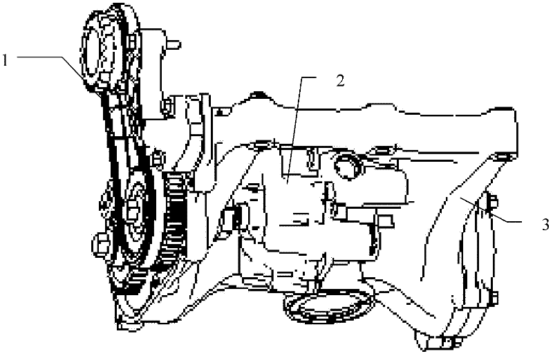
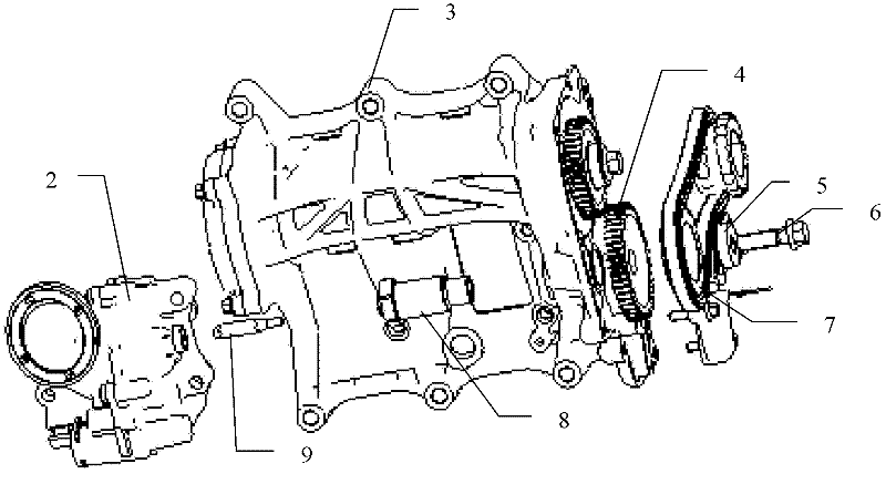
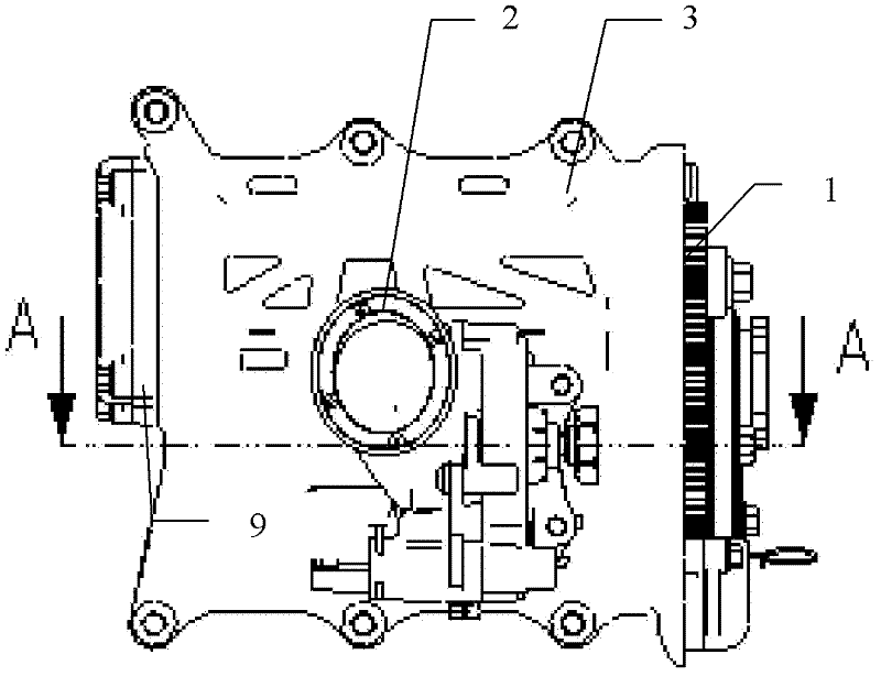
[0027] see figure 1 , figure 2 , image 3 and Figure 4 , a transmission structure of an oil pump, including an oil pump 2 and a balance shaft system 3, the oil pump 2 includes an oil pump rotor shaft 10, the balance shaft system 3 includes a balance shaft drive gear 4 and a balance shaft drive shaft 8, and the oil pump rotor shaft 10 is connected to the balance shaft drive shaft 8 through the drive shaft 9, the balance shaft drive shaft 8 is provided with the balance shaft drive gear 4, and the balance shaft drive gear 4 is connected to the sprocket system 1.

[0028] In the embodiment of the present invention, the drive gear of the balance shaft is driven by the sprocket system, and the drive gear of the balance shaft drives the ...


PUM


Abstract

The invention discloses a transmission structure of an oil pump, which comprises the oil pump and a balance shaft system. The oil pump comprises an oil pump rotor shaft, the balance shaft system comprises a balance shaft driving gear and a balance shaft driving shaft, the oil pump rotor shaft is connected with the balance shaft driving shaft through a driving shaft, and the balance shaft driving shaft is provided with the balance shaft driving gear connected with a chain wheel system. The transmission structure of the oil pump effectively connects a balance shaft and the oil pump in a driving mode through a hexagonal shaft, well and effectively composites the transmission of the balance shaft and the oil pump, can ensure the oil pump and the balance shaft to simultaneously and reliably work by only adopting one set of chain wheel driving system, and is simple in structure and convenient in assembly, disassembly and maintenance. Simultaneously, due to the fact that one set of chain wheel driving system is reduced, development cost is also reduced.

Description

technical field [0001] The invention relates to the field of automobile manufacturing, in particular to a transmission structure of an oil pump. Background technique [0002] The oil pump is one of the core parts of the engine lubrication system and plays a decisive role in the entire engine lubrication system. It provides sufficient pressure and flow of oil for the entire engine, so that the lubricating oil circulates continuously in the lubrication system to ensure that every One friction part is adequately lubricated, protecting the associated pressure-bearing parts from damage. [0003] At present, the arrangement of the oil pump in the engine lubrication system mainly has two structures: directly driven by the crankshaft and driven by a chain. Since the oil pump directly driven by the crankshaft is arranged at the outer end of the cylinder, it not only has high requirements for sealing, but also because it is directly connected to the crankshaft. Connection, the drivin...

Claims


Application Information

Patent Timeline
IPC IPC(8): F02B67/06F01M1/02
Inventor 倪伟付晓利
Owner CHERY AUTOMOBILE CO LTD
Why Eureka
Try Eureka