
Longitudinal-transverse cross-flow multi-rotor variable frequency combined fan

A vertical and horizontal cross-flow and cross-flow wind turbine technology, applied in non-variable-capacity pumps, mechanical equipment, machines/engines, etc., can solve the problems of increased noise, large head loss, waste of resources, etc., and achieve noise reduction and control. Easy, low running costs

Inactive Publication Date: 2012-06-27
刘刚
View PDF0 Cites 7 Cited by
  • Summary
  • Abstract
  • Description
  • Claims
  • Application Information

AI Technical Summary

Problems solved by technology

This air supply structure has the following defects: First, in the structure of the fan coil unit of the household air conditioner, due to the large diameter of the axial flow, the thickness of the inner unit of the air conditioner on the market is very large, which brings troubles to the actual design, installation, transportation, and actual life. , also because the fan increases the motor speed in order to ensure the air volume, resulting in increased noise; secondly, the axial flow fan is used in the air-conditioning cabinet machine. In order to ensure the air volume of the cabinet machine, the volume of the fan is larger, about 30×30×20, The air conditioner built for this purpose occupies about one square meter of land and about 1-2 cubic meters of space, which takes up a lot of indoor space and wastes resources.
Its disadvantages are: because the airflow is forced to turn inside the impeller, the pressure head loss is large and the efficiency is low; the outlet is directional and the wind speed is high, which can reach more than 8 meters, so in the suction structure, there will be a The wind speed of the tuyere is too high to be adjusted, and the wind speed is high, and it is difficult for people to adapt; when the wind speed is reduced, there is not enough air volume to meet the needs, which reduces the application range of the cross-flow fan product, and the manufacturer has to use other thicker air volume. Air supply structure

Method used


Image

  • Longitudinal-transverse cross-flow multi-rotor variable frequency combined fan
  • Longitudinal-transverse cross-flow multi-rotor variable frequency combined fan
  • Longitudinal-transverse cross-flow multi-rotor variable frequency combined fan

Examples


Embodiment Construction

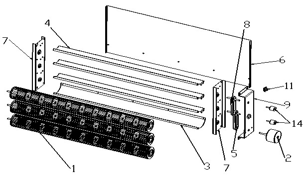
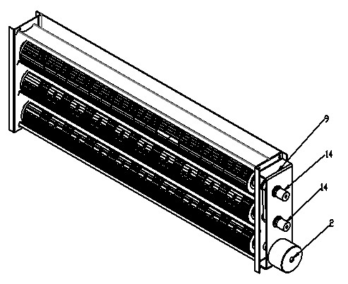
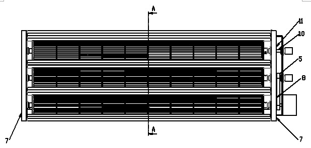
[0021] A vertical and horizontal cross-flow multi-wind wheel frequency conversion combined fan, including a side baffle 7 and a rear baffle 6, a number of connected cross-flow wind wheels 1 are arranged between the two side baffles 7, one of the cross-flow wind wheels 1 is connected to the motor 2, and the arrangement of the cross-flow wind wheels 1 is a horizontal parallel arrangement or a vertical parallel arrangement; the number of the cross-flow wind wheels 1 is not less than 2; the longitudinal parallel arrangement is a continuous The flow wind wheel 1 is connected by a synchronous pulley 5, a synchronous belt 8 and an electromagnetic clutch 14. The synchronous pulley 5 is sleeved on the transmission shaft 10, and one end of the transmission shaft 10 connected to the bracket 9 is movably connected to the electromagnetic clutch through a bearing 11. 14, the other end is connected with the cross-flow wind wheel 1, the volute tongue 4 is arranged between the cross-flow wind w...


PUM


Abstract

The invention discloses a longitudinal-transverse cross-flow multi-rotor variable frequency combined fan, which comprises side baffles (7) and a rear baffle (6). A plurality of connected cross-flow rotors (1) are disposed between the two side baffles (7). One cross-flow rotor (1) is connected with a motor (2). The cross-flow rotors (1) are in transverse linear parallel arrangement or longitudinal parallel arrangement. The longitudinal-transverse cross-flow multi-rotor variable frequency combined fan has the advantages that the fan is in a horizontal free-extension design, the vertical thickness is ultralow, air volume is high, noise is reduced greatly, and the fan is economical, energy-saving and long in service life.

Description

technical field [0001] The invention relates to a cross-flow fan in the field of heating and ventilation, in particular to a vertical and horizontal cross-flow multi-wind wheel frequency conversion combined fan. Background technique [0002] Existing fan structures are mostly used in air curtain machines, household and automobile air conditioners. In the field of air conditioning, in order to maintain the air volume of the indoor unit (the evaporator when cooling, and the condenser when heating), axial flow fans and centrifugal fans are respectively used as the air supply structure. Even if the fan structure on the market has double wind rotors, there are only two wind rotors on both sides in one product, and the diameter has not changed. This air supply structure has the following defects: First, in the structure of the fan coil unit of the household air conditioner, due to the large diameter of the axial flow, the thickness of the inner unit of the air conditioner on the...

Claims


Application Information

Patent Timeline
Patent Type & Authority Applications(China)
IPC IPC(8): F04D25/16
Inventor 刘刚
Owner 刘刚
Learn More