Micropore measurer based on orthogonal two-dimensional micro-focus collimation and method

A length measuring device and micro-focus technology, applied in measuring devices, optical devices, instruments, etc., can solve the problems of two-dimensional measurement error, insufficient detection ability of two-dimensional displacement direction, poor real-time performance of the detection system, etc., to eliminate correlation Effect

Inactive Publication Date: 2014-07-16
HARBIN INST OF TECH
View PDF5 Cites 0 Cited by
  • Summary
  • Abstract
  • Description
  • Claims
  • Application Information

AI Technical Summary

Problems solved by technology

[0013] 2. The detection system has no absolute "0" position in the measurement direction
[0014] 3. The real-time performance of the detection system is poor, and it is difficult to achieve precise online measurement
[0015] 4. Insufficient detection ability of two-dimensional displacement direction
The one-dimensional micro-focus alignment measurement method proposed by Harbin Institute of Technology based on single-fiber probe measuring rod has coupling in two-dimensional displacement sensing. When the measured displacement is two-dimensional displacement, the two-dimensional information obtained by this method There is a correlation between them, and they cannot be separated, resulting in a large error in the two-dimensional measurement, and the accurate measurement of the two-dimensional displacement cannot be realized

Method used


Image

  • Micropore measurer based on orthogonal two-dimensional micro-focus collimation and method
  • Micropore measurer based on orthogonal two-dimensional micro-focus collimation and method
  • Micropore measurer based on orthogonal two-dimensional micro-focus collimation and method

Examples


Embodiment Construction

[0033] Embodiments of the present invention will be described in detail below in conjunction with the accompanying drawings.

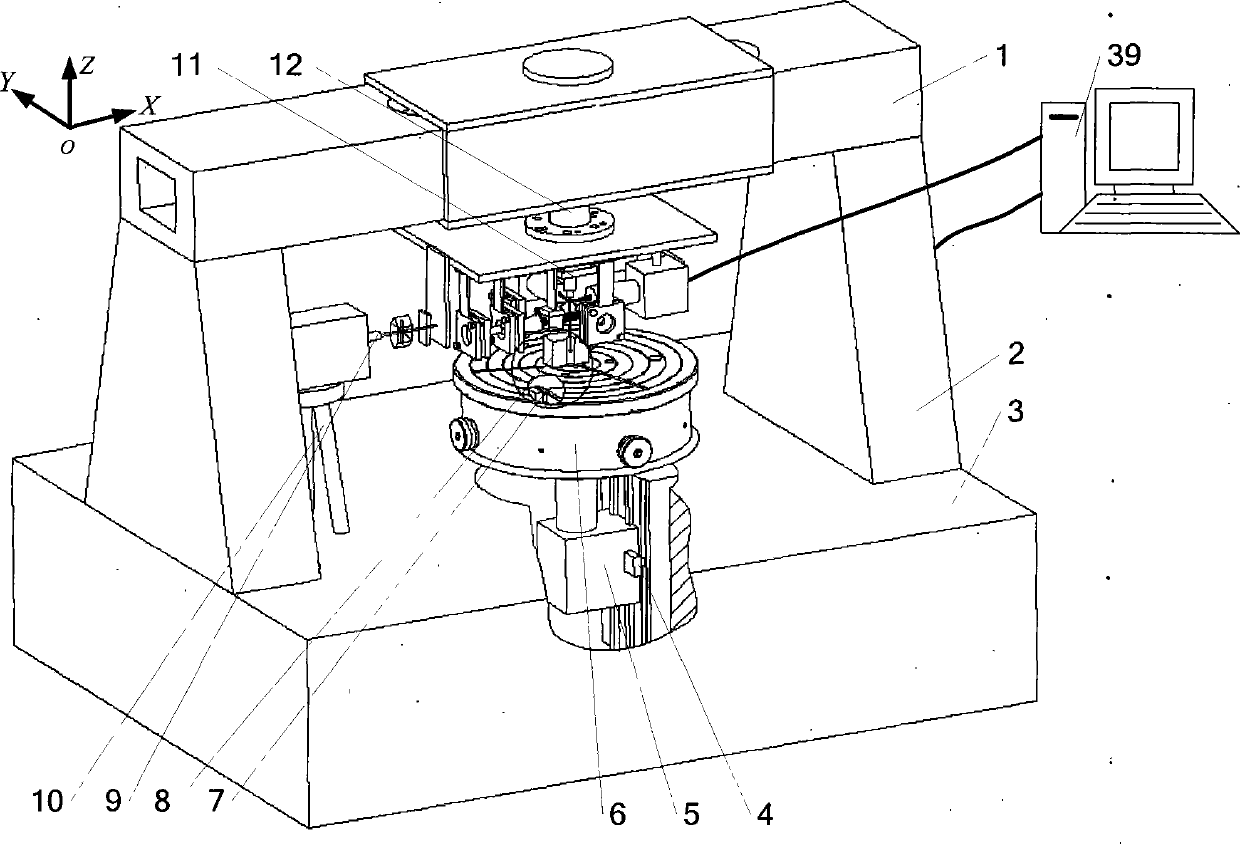
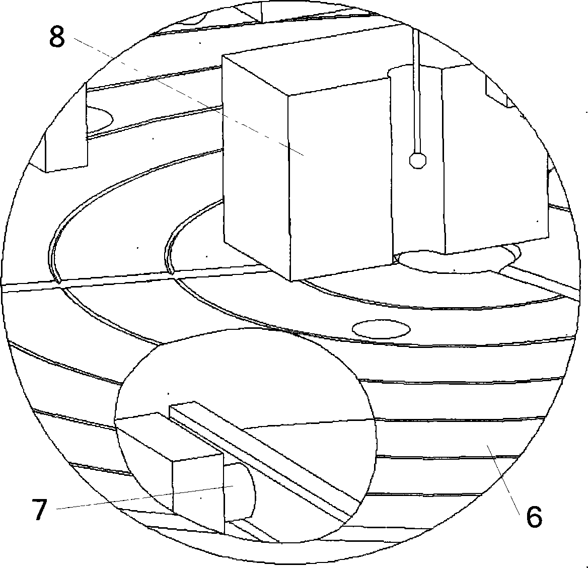
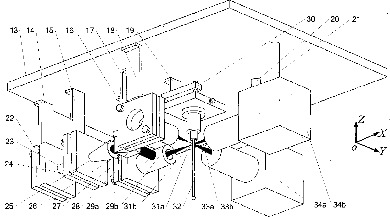
[0034]A microhole measurement device based on orthogonal two-dimensional microfocus alignment, two support frames 2 are assembled on the support base 3, a beam 1 is assembled on the support frame 2, and Z-direction movement is assembled in the groove of the support base 3 Part 5, the Z-direction length measuring device 4 is assembled on the side of the Z-direction moving part 5, and the worktable 6 is fixed above the Z-direction moving part 5, and the Y-direction length measuring device 7 is assembled inside the workbench 6, connected by a sensor Component 12 fixes and hangs the measuring sensor 11 on the middle position of the beam, and the dual-frequency laser 35, polarization beam splitter group 36, and λ / 4 glass slide 37 of the X-direction length measuring device 9 are assembled on the left side of the support base 3 through the tripod 10. In the s...


PUM


Abstract

A micropore measurer based on orthogonal two-dimensional micro-focus collimation and a method belong to the technical field of precision instrument manufacture and precision test metering. Two supporting frames are assembled on a supporting base, each supporting frame is provided with a crossbeam, a Z-direction movement component is assembled in a groove of the supporting base, a Z-direction length measuring device is assembled on a side surface of the Z-direction movement component, a worktable is fixed above the Z-direction movement component, a Y-direction length measuring device is assembled in the worktable, a measurement sensor is fixedly hung in the middles of the crossbeams, an X-direction length measuring device is located on the left side of the supporting base, a planar reflector is fixedly assembled on the left side of the measurement sensor, and the measurement sensor, the X-direction length measuring device, the Y-direction length measuring device and the Z-direction length measuring device are successively connected with a computer via data lines. In the method, the worktable continuously moves in a direction perpendicular to an appointed measurement direction, and the maximum value, which is measured repeatedly, of the distance between two contact measured points is the diameter of a measured micropore. The micropore measurer and the method have the advantages of zero sensing coupling, capability of realizing directional detection, small measuring force and the like.

Description

technical field [0001] The invention belongs to the technical field of precision instrument manufacturing and measurement, and in particular relates to a microhole measurement device and method based on orthogonal two-dimensional microfocus alignment. Background technique [0002] With the continuous development of the aerospace industry, automobile industry, electronics industry and cutting-edge industries, the demand for precision micro-cavity components has increased dramatically. Due to the limitation of the space scale and the influence of the measurement contact force, the precise measurement of the inner dimensions of the tiny inner cavity components has become difficult to achieve, especially the measurement depth is difficult to increase, which has become a "bottleneck" restricting the development of the industry. In order to achieve smaller internal dimension measurement and increase the measurement depth, the most widely used method is to use a slender probe to pr...

Claims


Application Information

Patent Timeline
Patent Type & Authority Patents(China)
IPC IPC(8): G01B11/03
Inventor 崔继文李俊英李磊杨福铃谭久彬
Owner HARBIN INST OF TECH
Why Eureka
Try Eureka