Orthogonal light path two-dimensional micro-focus collimation and three-dimensional coordinate sensor

A technology of three-dimensional coordinates and sensors, which is applied in the field of sensors, can solve the problems of increased data volume, low primary magnification, and difficulty in achieving synchronization of small inner cavity sizes, and achieve the effect of long working distance and large working space

Inactive Publication Date: 2012-07-18
HARBIN INST OF TECH
View PDF4 Cites 29 Cited by
  • Summary
  • Abstract
  • Description
  • Claims
  • Application Information

AI Technical Summary

Problems solved by technology

[0012] 1. It is difficult to further improve the displacement resolution of the detection system
The primary magnification of the existing detection system is low, resulting in a low overall magnification, and it is difficult to further improve its displacement resolution
The optical path magnification of the optical measuring rod used in the detection method adopted by the National Institute of Standards and Technology is only 35 times, and the low primary magnification makes it difficult to further improve the displacement resolution.
[0013] 2. The detection system has no absolute "0" position in the measurement direction
The existing detection methods for tiny inner cavities mainly judge the displacement of the optical fiber measuring rod through the two-dimensional images received by the area array CCD. This method does not have an absolute "0" position, which makes it difficult for the detection system to distinguish the polarity of the measurement elements. It is also difficult to obtain higher measurement repeatability
[0014] 3. The real-time performance of the detection system is poor, and it is difficult to achieve precise online measurement
The detection method adopted by the National Institute of Standards and Technology must use two-way area array CCDs to receive signal images, and since the magnification of the imaging optical path of the optical fiber measuring rod is only 35 times, a more complex image algorithm must be used to achieve high displacement of the optical fiber measuring rod. Resolution monitoring, which leads to a large increase in the amount of data that the measurement system needs to process, reduces the real-time performance of the detection system, and makes it difficult to realize the synchronization of the aiming signal and the start and stop measurement in the process of small inner cavity size and two-dimensional coordinate measurement
[0015] 4. Insufficient detection ability of two-dimensional displacement direction
The one-dimensional micro-focus alignment measurement method proposed by Harbin Institute of Technology based on single-fiber probe measuring rod has coupling in two-dimensional displacement sensing. When the measured displacement is two-dimensional displacement, the two-dimensional information obtained by this method There is a correlation between them, and they cannot be separated, resulting in a large error in the two-dimensional measurement, and the accurate measurement of the two-dimensional displacement cannot be realized

Method used


Image

  • Orthogonal light path two-dimensional micro-focus collimation and three-dimensional coordinate sensor
  • Orthogonal light path two-dimensional micro-focus collimation and three-dimensional coordinate sensor
  • Orthogonal light path two-dimensional micro-focus collimation and three-dimensional coordinate sensor

Examples


Embodiment Construction

[0033] The embodiments of the present invention will be described in detail below with reference to the accompanying drawings.

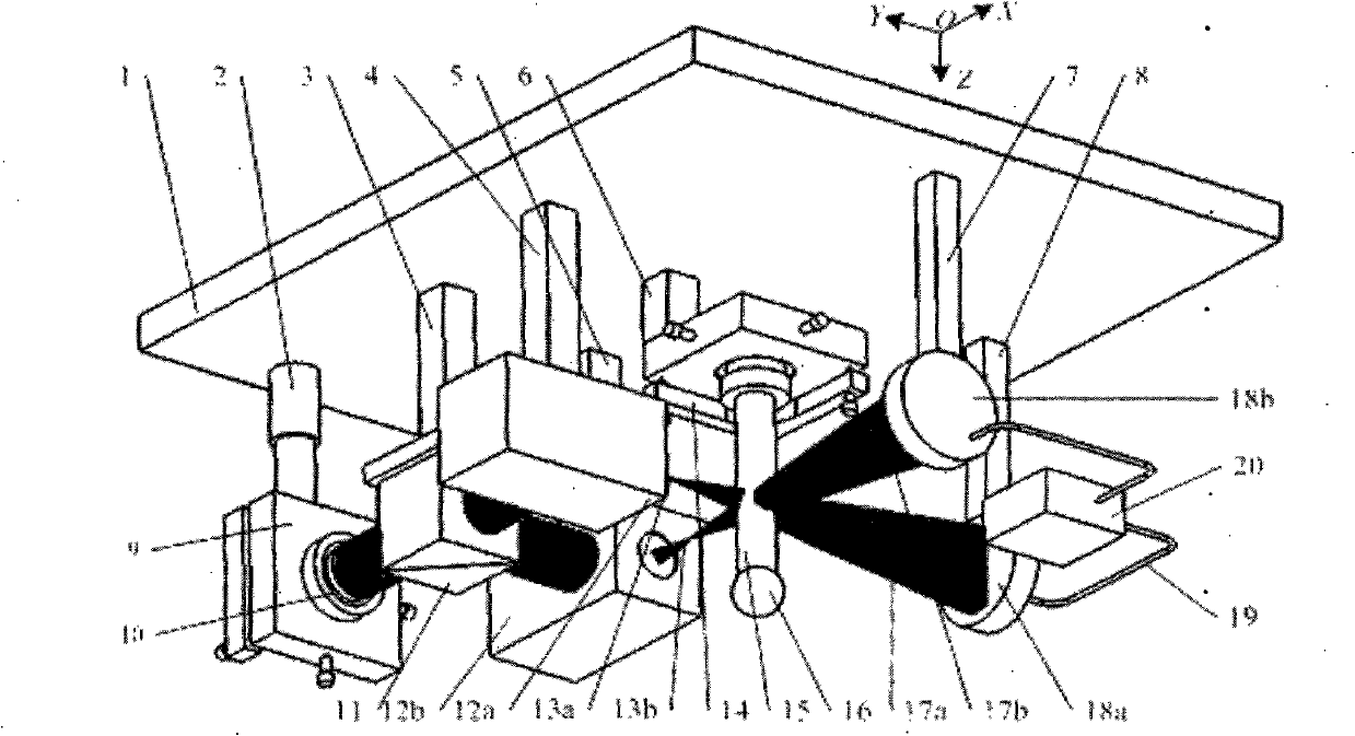
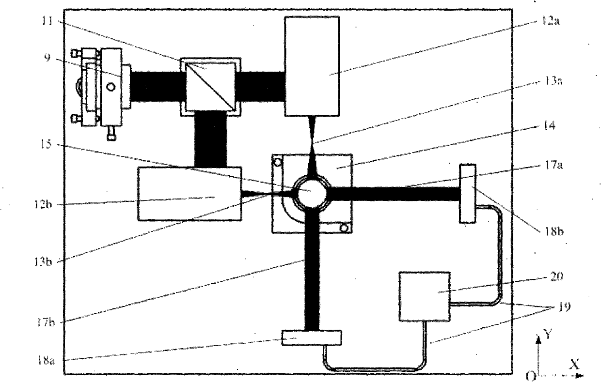
[0034] An orthogonal optical path two-dimensional micro-focus collimator and three-dimensional coordinate sensor. The first connecting frame 2, the second connecting frame 3, the third connecting frame 4, the fourth connecting frame 5, and the fifth connecting frame are installed on the assembly table 1. 6. The sixth connecting frame 7 and the seventh connecting frame 8, four-dimensional adjustment frame 9, beam splitter 11, reflex telephoto system A12a, reflex telephoto system B12b, five-dimensional adjustment frame 14, photoelectric receiver B18b, The photoelectric receiver A18a is respectively assembled on the first connection frame 2, the second connection frame 3, the third connection frame 4, the fourth connection frame 5, the fifth connection frame 6, the sixth connection frame 7 and the seventh connection frame 8. The laser light source 10 is as...


PUM


Abstract

The invention relates to an orthogonal light path two-dimensional micro-focus collimation and three-dimensional coordinate sensor, belonging to a sensor. A first to a seventh connecting frames are arranged on an assembly platform in sequence; a four-dimensional adjusting frame, a spectroscope, a refracting-reflecting type long-focus system A, a refracting-reflecting type long-focus system B, a photoelectric receiver B and a photoelectric receiver A are respectively assembled on the first to the seventh connecting frame; a laser source is assembled on the four-dimensional adjusting frame; an optical fiber probe measuring bar provided with an optical fiber probe measuring head is arranged on a five-dimensional adjusting frame; and the photoelectric receiver A and the photoelectric receiver B are respectively connected with a data acquisition processor through data transmission lines. The orthogonal light path two-dimensional micro-focus collimation and three-dimensional coordinate sensor has the characteristics of zero coupling of two-dimensional sensing information, capability of carrying out detection in the two-dimensional direction, small measuring force, easy minimization, large measured ratio of pit-depth to pit-diameter, good real-time property and easy application, and has remarkable advantages in implementation of rapid and ultra-precise measurement and calibration on micro inside dimensional and three-dimensional coordinates.

Description

Technical field [0001] The invention belongs to a sensor, and mainly relates to an orthogonal optical path two-dimensional micro-focus collimator that can go deep into a micro-deep inner cavity and convert the touch position information of an optical fiber probe probe and the inner cavity side wall into position information of the beam energy center With three-dimensional coordinate sensor. Background technique [0002] With the continuous development of the aerospace industry, automobile industry, electronics industry, and cutting-edge industries, the demand for precision micro-cavity components has increased dramatically. Due to the limitation of the spatial scale and the influence of the measuring contact force, the precise measurement of the inner dimensions of the tiny internal cavity components has become difficult to achieve, especially the measurement depth is difficult to increase, which has become a "bottleneck" restricting the development of the industry. In order to ...

Claims


Application Information

Patent Timeline
Patent Type & Authority Applications(China)
IPC IPC(8): G01B11/00
Inventor 崔继文李磊李俊英杨福铃谭久彬
Owner HARBIN INST OF TECH
Why Eureka
Try Eureka