Manufacturing method of electroluminescence test electrode

A technology for testing electrodes and manufacturing methods, applied in measurement devices, measuring electrical variables, manufacturing measuring instruments, etc., can solve problems such as differences, poor optical power test repeatability, poor test repeatability, etc., and achieve convenient, reliable and stable photoelectric test results. , the effect of improving repeatability

Inactive Publication Date: 2014-02-19
ADVANCED OPTRONIC DEVICES CHINA
View PDF5 Cites 0 Cited by
  • Summary
  • Abstract
  • Description
  • Claims
  • Application Information

AI Technical Summary

Problems solved by technology

[0004] Disadvantages of the existing technology: Before each measurement using the electroluminescence tester, the P (positive) electrode and the N (negative) electrode must be prepared first. After the first measurement, the indium particles on the epitaxial wafer need to be removed and re-made electrode, and then conduct the second test, however, there is a large difference between the second measured result and the first time, and the test repeatability is poor, mainly due to the poor test repeatability of optical power

Method used


Image

  • Manufacturing method of electroluminescence test electrode
  • Manufacturing method of electroluminescence test electrode
  • Manufacturing method of electroluminescence test electrode

Examples


Embodiment 1

[0021] A method for manufacturing an electroluminescence test electrode, comprising the following steps:

[0022] (1) Select a batch of indium particles with a diameter of 0.65mm, and the diameter tolerance is within 5%;

[0023] (2) Use a fixed pressure on the epitaxial wafer to press the above-mentioned indium particles with a constant force, and the tolerance of the pressure is less than 1%; the material for pressing the indium particles is the polished surface of the aluminum oxide substrate, and the roughness is Ra≥5um;

[0024] (3) Then heat the indium particles at 380°C for 2 minutes, cool for 1 minute, press for 5 seconds, and cycle 3 times to stabilize the resistance between the indium particles and the epitaxial wafer, and the tolerance of voltage and resistance is less than 5%. ;

[0025] (4) Finally, test on the electroluminescence tester.

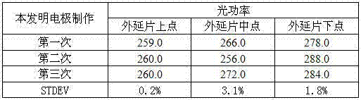
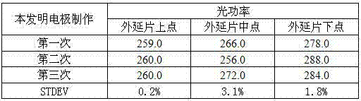
[0026] The optical power results of the test are shown in the table below.

[0027] Table 1 adopts the electrode manufactu...

Embodiment 2

[0034] A method for manufacturing an electroluminescence test electrode, comprising the following steps:

[0035] (1) Select a batch of indium particles with a diameter of 0.30mm, and the diameter tolerance is within 5%;

[0036] (2) Use a fixed pressure on the epitaxial wafer to press the above-mentioned indium particles with a constant force, and the tolerance of the pressure is less than 1%; the material for pressing the indium particles is the polished surface of the aluminum oxide substrate, and the roughness is Ra≥5um;

[0037] (3) Heat the indium pellets at 400°C for 1 minute, cool for 0.5 minutes, press for 2 seconds, and cycle twice to stabilize the resistance between the indium pellets and the epitaxial wafer, and the tolerance of voltage and resistance is less than 5%;

[0038] (4) Finally, test on the electroluminescence tester.

[0039] The measured optical power results are shown in Table 3.

[0040] Table 3 adopts the electrode manufacturing method of the pres...

Embodiment 3

[0044] A method for manufacturing an electroluminescence test electrode, comprising the following steps:

[0045] (1) Select a batch of indium particles with a diameter of 0.65mm, and the diameter tolerance is within 5%;

[0046] (2) Use a fixed pressure on the epitaxial wafer to press the indium pellets with a constant force, and the tolerance of the pressure is less than 1%; the material for pressing the indium pellets is the polished surface of the aluminum oxide substrate, and the roughness is Ra≥5um;

[0047] (3) Heat the indium particles at 350°C for 3 minutes, cool for 2 minutes, press each electrode for 8 seconds, and cycle twice to stabilize the resistance between the indium particles and the epitaxial wafer, and the tolerance of voltage and resistance is less than 5 %;

[0048] (4) Finally, test on the electroluminescence tester.

[0049] The measured optical power results are shown in Table 4.

[0050] Table 4 adopts the electrode manufacturing method of the pres...


PUM


Abstract

The invention discloses a manufacturing method of an electroluminescence test electrode. The method comprises the following steps: selecting indium granular with a same size; using a fixed pressure to carry out constant force pressing indium granular on an epitaxial wafer; repeatedly carrying out heating, cooling, the constant force pressing to the indium granular so that a resistance between the indium granular and the epitaxial wafer can reach stability. The invention has the following advantages that: the manufacturing method is simple; usage is convenient; through repeatedly carrying out the heating, the cooling, the constant force pressing to the indium granular, repeatability of the test can be substantially increased and a repeatability standard deviation can be controlled in 0-4% so that a reliable and stable photoelectric test result can be obtained.

Description

technical field [0001] The invention relates to a method for manufacturing an electrode, in particular to a method for manufacturing an electroluminescence test electrode, which belongs to the field of LED test electrodes. Background technique [0002] After the epitaxial wafer is grown, it is necessary to quickly and accurately measure its photoelectric parameters with an electroluminescence tester, and then adjust various parameters of the epitaxial growth program according to the measurement results, so as to achieve the purpose of continuously optimizing the epitaxial structure. [0003] The current electrode production scheme includes the following steps: ①select indium grains of uniform size; ②press the indium grains on the epitaxial wafer; ③heat to reduce the contact resistance between the indium grains and the epitaxial wafer; ④test with an electroluminescence tester. [0004] Disadvantages of the existing technology: Before each measurement using the electroluminesc...

Claims


Application Information

Patent Timeline
Patent Type & Authority Patents(China)
IPC IPC(8): G01R3/00
Inventor 孙德亮刘凯
Owner ADVANCED OPTRONIC DEVICES CHINA
Why Eureka
Try Eureka