
Three-dimensional imaging method for three-dimensional imaging system with cylindrical array surface

A technology of three-dimensional imaging and imaging system, which is applied in the field of three-dimensional imaging, can solve problems affecting imaging quality, inconsistent delay time, single-channel amplitude-frequency error, etc., and achieve the effect of good image quality, high resolution and clear display

Active Publication Date: 2012-06-27
BEIJING HUAHANG HAIYING NEW TECH DEV
View PDF2 Cites 14 Cited by
  • Summary
  • Abstract
  • Description
  • Claims
  • Application Information

AI Technical Summary

Problems solved by technology

[0006] The first method is not suitable for engineering applications, and regardless of the second or third method above, the amplitude-frequency consistency of the large-bandwidth signal and the linearity of the signal are non-ideal, that is, there is poor linearity of the chirp signal 1. Single-channel amplitude-frequency error; due to the use of multiple transceiver channels, the amplitude of echo signals between different channels is inconsistent, and the delay time of different channels is inconsistent, resulting in echo frequency deviation and phase error. If these problems are not resolved, the imaging quality will be seriously affected.

Method used


Image

  • Three-dimensional imaging method for three-dimensional imaging system with cylindrical array surface
  • Three-dimensional imaging method for three-dimensional imaging system with cylindrical array surface
  • Three-dimensional imaging method for three-dimensional imaging system with cylindrical array surface

Examples


Embodiment Construction

[0025] The current three-dimensional imaging security inspection systems with cylindrical arrays all work in the microwave or millimeter wave band and have the characteristics of large bandwidth, which leads to non-ideality in the amplitude-frequency consistency and signal linearity of large-bandwidth signals, that is, there is chirp frequency modulation Poor signal linearity, large single-channel amplitude-frequency error, inconsistent echo signal amplitudes between different channels, and inconsistent delay times of different channels lead to echo frequency deviation and phase errors, which seriously affect the image quality of 3D imaging.

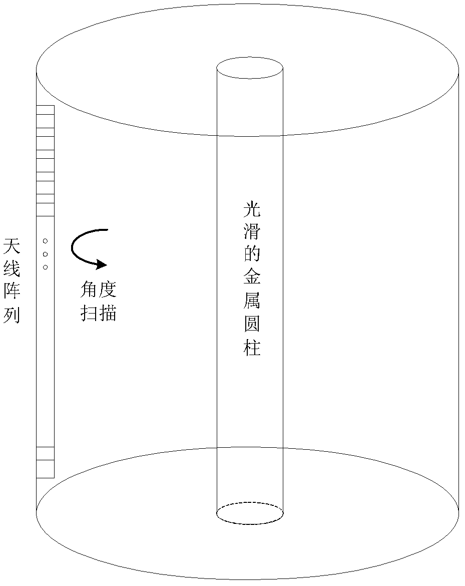
[0026] A typical cylindrical array 3D imaging system includes: motor, servo controller, antenna array disk bracket, transmitting antenna array, receiving antenna array, frequency synthesis module, echo signal receiving and processing device, signal processor, memory, etc.

[0027] The transmitting antenna array is used to radiate radio fr...


PUM

PropertyMeasurementUnit
Radiusaaaaaaaaaa
Radiusaaaaaaaaaa

Abstract

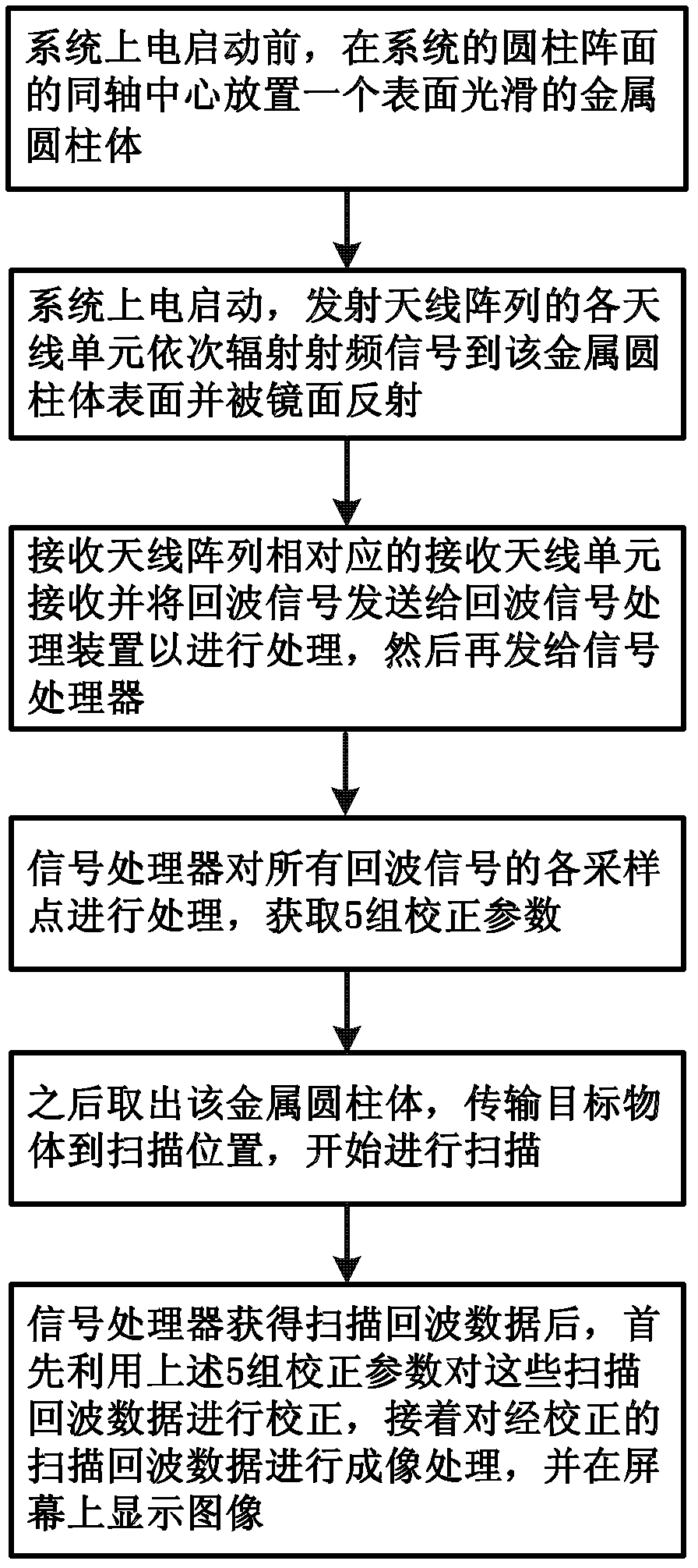
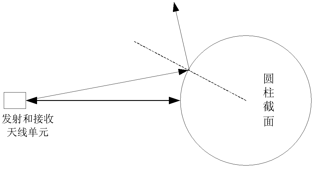
The invention relates to a three-dimensional imaging method for a three-dimensional imaging system with a cylindrical array surface, which includes: placing a metal cylinder with a smooth surface at the coaxial center of the cylindrical array surface of the system before powering on the system; powering on N transmitting antenna units to sequentially transmit radio frequency signals to the surface of the metal cylinder and to be reflected by a mirror; receiving echo signals and transmitting the echo signals to an echo signal receiving and processing device by the aid of corresponding receiving antenna units to process the echo signals and then transmit the echo signals to a signal processor; processing all the echo signals after receiving and digitally sampling all the echo signals by theaid of the signal processor to obtain and store five groups of correction parameters; taking out the metal cylinder, transmitting a target object to a scanning position, starting scanning and transmitting echo signals; and correcting scanning echo signal data by using the five groups of correction parameters, imaging the corrected scanning echo signal data by a known three-dimensional imaging method and then displaying images on a screen by the aid of the signal processor.

Description

technical field [0001] The patent of the present invention relates to the field of three-dimensional imaging, and specifically relates to a three-dimensional imaging method of a cylindrical array three-dimensional imaging system. Background technique [0002] With the development of science and technology, humans have developed many new means of transportation, such as airplanes, high-speed trains, subways, etc. These means of transportation carry a large number of people. Once dangerous goods enter the means of transportation, it is very easy to bring safety hazards. Threat to the lives of those around you. For example, carrying flammable and explosive items into the plane or subway, etc. [0003] In addition, as human social activities become more and more extensive, large-scale gatherings are often held, and these large-scale gatherings often gather tens of thousands of people. Once someone enters with dangerous objects or terrorists enter with explosives to carry out t...

Claims


Application Information

Patent Timeline
IPC IPC(8): G01S13/90G01S7/40
Inventor 张炳煌陈晔张远航
Owner BEIJING HUAHANG HAIYING NEW TECH DEV
Learn More