
Memory circuit

A memory circuit and circuit technology, applied in the field of circuits, can solve problems such as increased test cost and large clamping circuit area, and achieve the effects of improving reliability and service life and ensuring the stability of threshold window.

Active Publication Date: 2015-01-07
SHANGHAI FUDAN MICROELECTRONICS GROUP
View PDF5 Cites 0 Cited by
  • Summary
  • Abstract
  • Description
  • Claims
  • Application Information

AI Technical Summary

Problems solved by technology

The clamping circuit has good temperature characteristics and can achieve a constant clamping voltage within the operating temperature range. However, the clamping voltage is mainly determined by the bandgap reference source. The accuracy of the bandgap reference source is greatly affected by the process. To achieve higher accuracy, it needs Configure each chip when testing, which will increase the cost of testing, and the area of ​​the clamping circuit itself is also large

Method used


Image

  • Memory circuit
  • Memory circuit
  • Memory circuit

Examples


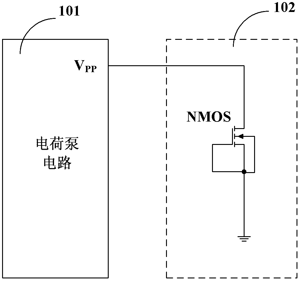
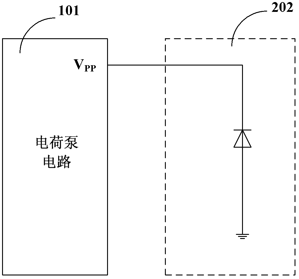
Embodiment Construction

[0026] In order to make the above objects, features and advantages of the present invention more comprehensible, specific implementations of the present invention will be described in detail below in conjunction with the accompanying drawings.

[0027] In the following description, many specific details are set forth in order to fully understand the present invention, but the present invention can also be implemented in other ways than those described here, so the present invention is not limited by the specific embodiments disclosed below.

[0028] As mentioned in the background technology section, non-volatile memory circuits such as EEPROM and FLASH need to generate an erasing voltage higher than 10V inside the chip. The magnitude of the erasing voltage will affect the threshold window of the memory cell, and will also affect the memory cell and high-voltage circuits. Transistor reliability. The existing clamping circuit using NMOS transistors or diodes cannot guarantee the...


PUM


Abstract

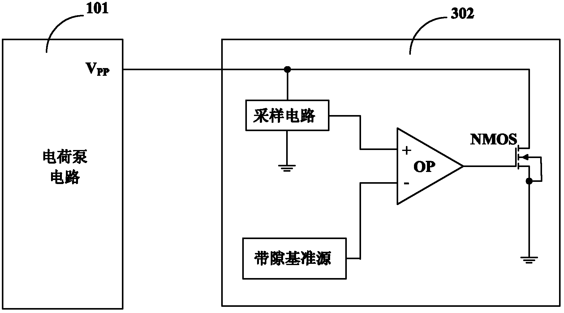
A memory circuit comprises a memory unit array and a peripheral circuit. The peripheral circuit consists of a charge pump circuit and a clamping circuit connected with the charge pump circuit, the clamping circuit comprises an overvoltage protection module and a clamping module which are connected in parallel, the overvoltage protection module is used for protecting an MOS (metal oxide semiconductor) transistor in a high-voltage circuit of a memory, the clamping module is used for clamping output voltage of the charge pump circuit, and an output end of the charge pump circuit is coupled to a first end of the clamping module. The memory circuit simultaneously guarantees reliability of threshold windows of memory units, reliability of the memory units and reliability of the transistor in the high-voltage circuit, and constant clamping voltage within a working temperature range can be realized.

Description

technical field [0001] The invention relates to the field of circuits, in particular to memory circuits. Background technique [0002] Non-volatile memory circuits such as EEPROM (Electrically Erasable Programmable Read-Only Memory) and FLASH need to generate an erasing voltage higher than 10V inside the chip, and use F-N tunneling effect or channel hot electron injection (CHEI) effect to EEPROM or FLASH memory performs erase and write operations, and the magnitude of the erase and write voltage will affect the threshold window of the memory cell, and will also affect the reliability of the memory cell and the reliability of the transistor in the high-voltage circuit used to control the operation in the memory. [0003] The EEPROM or FLASH memory circuit includes a memory cell array and peripheral circuits. The peripheral circuit includes a charge pump circuit. The charge pump circuit outputs an erasing voltage to perform erasing and writing operations on the EEPROM or FLASH...

Claims


Application Information

Patent Timeline
Patent Type & Authority Patents(China)
IPC IPC(8): G11C16/06
Inventor 刘岐马庆容沈晔晖倪成峰俞惠芬张之本满佳喜
Owner SHANGHAI FUDAN MICROELECTRONICS GROUP
Learn More