Building-block-combined-type high power transformer

A combined, high-power technology, applied in the direction of transformers, fixed transformers, transformer/inductor cores, etc., can solve problems such as expensive production costs, transformer overheating, primary coil temperature rise, etc., to save eddy current losses, reduce costs, space-saving effect

Inactive Publication Date: 2012-06-27
YUJING TECH CO LTD
View PDF8 Cites 1 Cited by
  • Summary
  • Abstract
  • Description
  • Claims
  • Application Information

AI Technical Summary

Problems solved by technology

Due to the continuous advancement of technology and the demand for high brightness of LCD displays, some manufacturers have increased the number of lamps used in the backlight module of the LCD display, and the number of transformers used will also increase. In this way, Not only does it cause the volume of the liquid crystal display to become larger, but the relative weight also becomes heavier.
Therefore, some operators will use a single transformer to drive multiple lamps. If the transformer mentioned above is used to drive multiple lamps, the voltage of the transformer must be increased to match its high power output; if so, use a single transformer to drive When there are multiple lamp tubes, the primary coil and the secondary coil are all wound on the same bobbin, so that the winding area of ​​the primary coil is limited. Therefore, if the voltage output is increased according to the needs of the transformer, the primary wire area and the secondary wire area The number of coils on the transformer must become larger, which leads to an increase in the thickness of the transformer and a relative increase in its overall volume
[0004] Secondly, when the load power increases, the primary coil part will have an obvious temperature rise problem, which may cause the transformer to overheat
If the wire diameter of the primary side winding coil is thickened, the problem of temperature rise can be solved slightly, but the thickness of the coil is increased, which makes the thickness of the transformer even more; in addition, in the above common transformers, if it is necessary to consider The safety isolation of the primary coil and the secondary coil on the same bobbin is more difficult in the withstand voltage of the high-voltage winding, which has a relatively adverse impact on the manufacturing and cost of transformer parts
In addition, for high-power transformers, large-scale iron cores need to be produced, and large-scale die-casting machines must be used to produce them, which makes the production cost relatively expensive. Therefore, how to solve the above problems has always been an urgent solution and improvement that the industry needs to seek.

Method used


Image

  • Building-block-combined-type high power transformer
  • Building-block-combined-type high power transformer
  • Building-block-combined-type high power transformer

Examples


Embodiment Construction

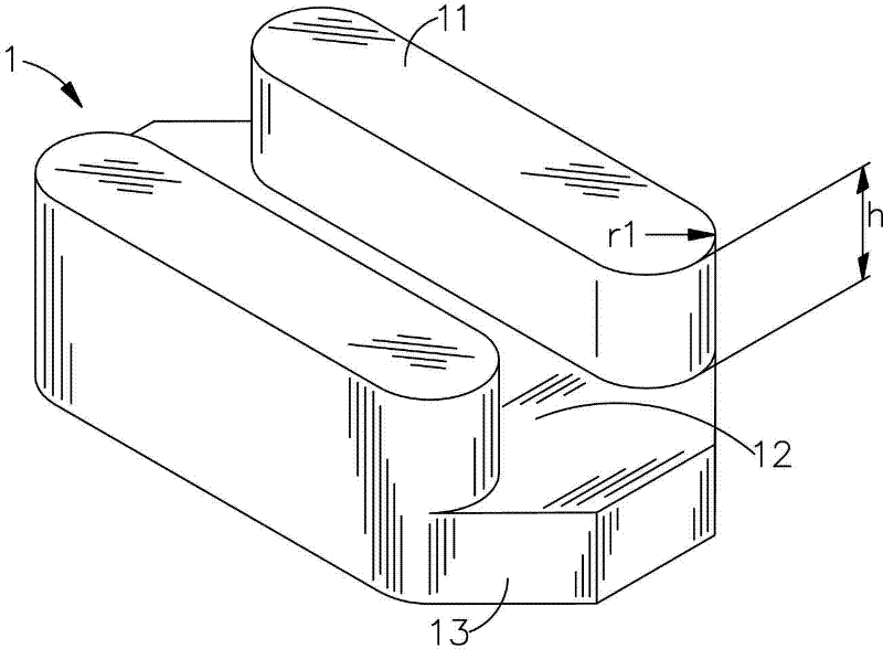
[0038] see figure 1 As shown, it is a schematic diagram of a three-dimensional structure of a preferred embodiment of a single iron core body of the present invention. The iron core body 1 of the present invention has a polygonal shape. In a preferred embodiment of the present invention, the iron core body 1 is an octagonal shape and is made of a conductive material. The two sides of this iron core body 1 respectively have a side wing part 11, and the two ends of the side wing part 11 are in the shape of an arc with a curvature radius r1, and a slot 12 is formed between the aforementioned two side wing parts 11, and the slot 12 The top surface of and the top surface of the side wing portion 11 are separated by a height h. Two ends of the iron core body 1 respectively have at least one inclined slot 13 .

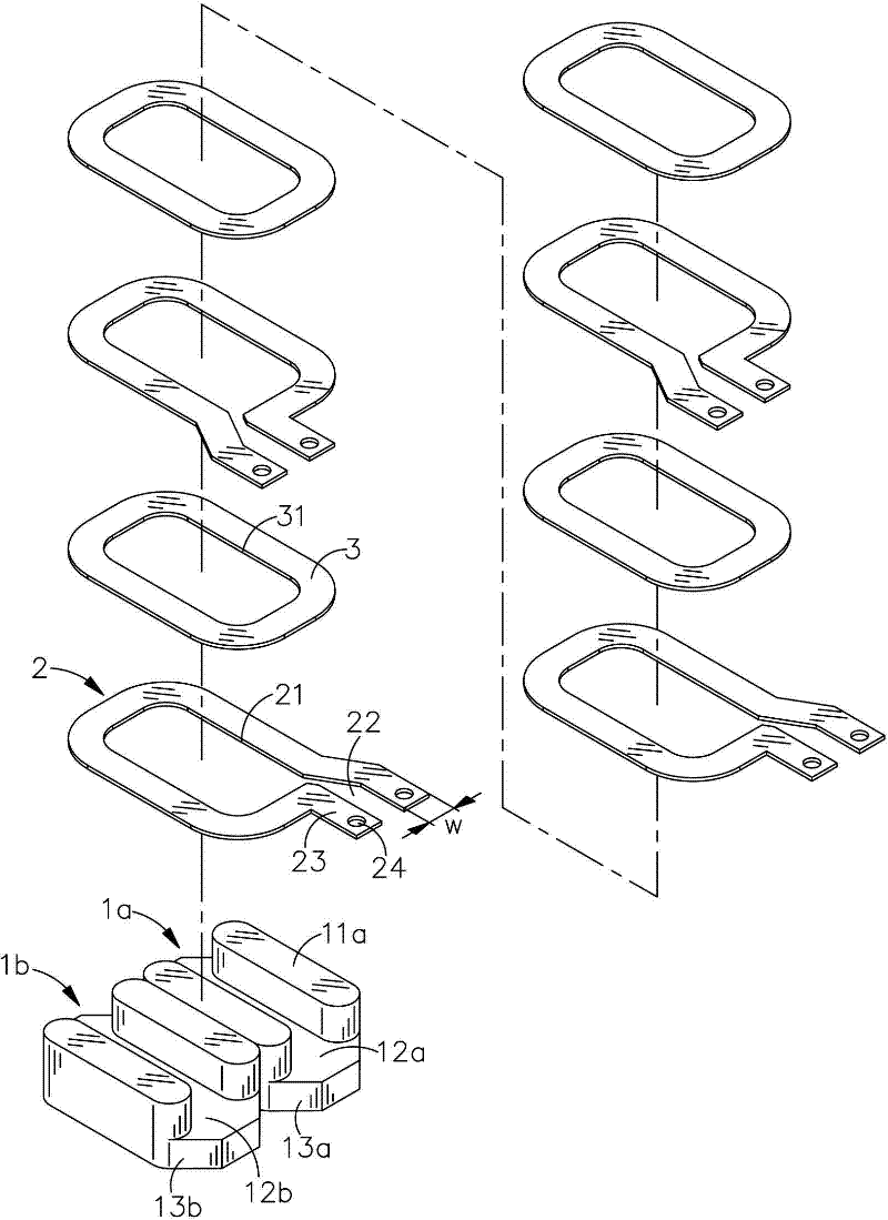
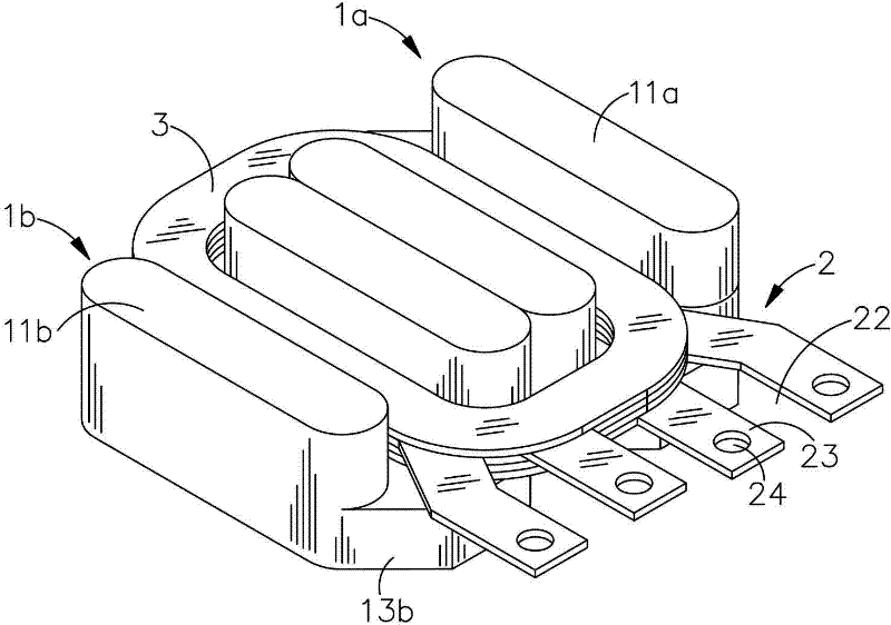
[0039] Since the building block combined high-power transformer of the present invention is formed by arranging and combining a plurality of aforementioned iron core bodies...


PUM


Abstract

A building-block-combined-type high power transformer includes a first iron core body, a second iron core body, a plurality of plate bodies, and a plurality of isolating bodies. The first iron core body and the second iron core body have a first side wing part and a second side wing part respectively at both sides thereof. Both of the first side wing part and the second side wing part being a circular shape at both ends respectively thereof have a first open channel and a second open channel formed between thereof where the second iron core body is in contact with the first iron core body. Each of the plate bodies being positioned in both the first open channel and second open channel has an open hole, for containing both of the first side wing part, and the second side wing part, and a guided channel that is positioned on the second side of the open hole. The isolating bodies being annular in shape and being positioned in between the first plate bodies and the second plate bodies have a through hole corresponding to the open hole for containing the first side wing part and the second side wing part.

Description

technical field [0001] The invention relates to a transformer structure, in particular to a building block combination high-power transformer used in large wattage (more than 3000 watts) by using the principle of building block combination. Background technique [0002] In recent years, due to the rapid development of high-tech technology, especially in the field of microelectronics related technology and process, electronic related products have penetrated into every family and all walks of life and become an indispensable part of modern life. [0003] The traditional transformer used to drive the backlight module lamp inside the liquid crystal display (LCD) has a coil base, which has a primary line area and a secondary line area, and a plurality of terminals are provided at both ends for connecting the wires of the winding and soldering to the circuit. plate. Due to the continuous advancement of technology and the demand for high brightness of LCD displays, some manufactu...

Claims


Application Information

Patent Timeline
Patent Type & Authority Applications(China)
IPC IPC(8): H01F27/26H01F27/245H01F41/02
CPCH01F27/38H01F27/2847H01F3/10H01F38/08H01F27/306H01F30/06H01F38/10
Inventor 潘正友
Owner YUJING TECH CO LTD
Why Eureka
Try Eureka