Multi-partition gas conveying apparatus

A conveying device and multi-partition technology, which is applied to electrical components, discharge tubes, circuits, etc., can solve the problems of increasing production costs, complicated system layout and control of plasma treatment devices, and achieve the effects of saving production costs and simple control.

Active Publication Date: 2012-06-27
ADVANCED MICRO FAB EQUIP INC CHINA
View PDF4 Cites 10 Cited by
  • Summary
  • Abstract
  • Description
  • Claims
  • Application Information

AI Technical Summary

Problems solved by technology

[0004] Although if more areas are divided on the shower head 300, the uniformity control of the plasma can be made more precise, but for each additional area, it is necessary to independently configure an air inlet channel 100 for this ar

Method used


Image

  • Multi-partition gas conveying apparatus
  • Multi-partition gas conveying apparatus
  • Multi-partition gas conveying apparatus

Examples


Example Embodiment

[0023] The specific embodiments of the present invention will be described below in conjunction with the drawings.

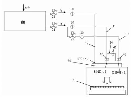
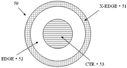
[0024] Such as figure 2 As shown, the multi-zone gas delivery device of the present invention is used to adjust the uniformity of the surface treatment of the wafer 70. The gas delivery device is connected to the shower head 50 on the top of the reaction chamber in the plasma processing device; the gas delivery device adjusts the two reaction gases into three channels with controllable flow, and correspondingly delivers them to the shower head 50. Three gas distribution zones 51, 52 and 53.

[0025] The two reactant gases transported in the device described in the following embodiments are separated from the same reactant gas. For example, one reactant gas is transported to a reactant gas regulator 60, and the reactant gas passes through the reactant gas regulator 60. After the corresponding adjustment of the installed gas separator and the flow controller (MFC), t...


PUM


Abstract

A gas conveying apparatus comprises a reaction gas regulator which outputs controllable flow reaction gas. A first gas pipeline conveys the reaction gas of first flow to a first and a second gas distribution areas through a first and a second current limiting apparatuses respectively. A third gas pipeline is communicated with the first gas pipeline through a controllable valve and is communicated with the first gas distribution area through a third current limiting apparatus. A second gas pipeline conveys the reaction gas of the second flow to a third gas distribution area. According to the invention, distribution control of multipath reaction gases with different flow ratios in a plurality of areas on a spray header can be realized so that uniform plasma processing effects can be obtained on a wafer surface. A selector switch is formed by a valve and the like. Two states: opening and closing should be only possessed. The apparatus is easy to be controlled. And setting cots of the valve and an orifice is lower than the cost of a MFC. A lot of production cost can be saved.

Description

technical field [0001] The invention relates to a gas conveying device, in particular to a multi-zone gas conveying device which realizes distribution control of introduced reaction gas through the combined arrangement of switches and flow-limiting holes. Background technique [0002] At present, in the process of manufacturing semiconductor devices, the reaction gas is generally transported through the shower head or similar device installed on the upper part of the reaction chamber, and enters the reaction chamber to form plasma for etching, deposition and other processing of the wafer. Due to various reasons such as gas transportation, electric field action or uneven pumping, the generated plasma is likely to be unevenly distributed at the center and edge of the wafer, which has a great impact on the reaction effect and reaction efficiency of different regions on the wafer surface. [0003] In order to solve this problem, the existing figure 1 In the shown plasma process...

Claims


Application Information

Patent Timeline
IPC IPC(8): H01J37/32
Inventor 倪图强魏强徐朝阳
Owner ADVANCED MICRO FAB EQUIP INC CHINA
Why Eureka
Try Eureka