Siphon-type degreasing furnace

A degreasing furnace and siphon type technology, applied in the field of siphon degreasing furnaces, can solve the problems of inconvenient use and maintenance, slow degreasing speed, inconvenience in taking out finished products, etc., and achieve the effect of convenient replacement and maintenance and increase degreasing speed.

Inactive Publication Date: 2013-07-31
宝得粉末注射成形(常熟)有限公司
View PDF9 Cites 0 Cited by
  • Summary
  • Abstract
  • Description
  • Claims
  • Application Information

AI Technical Summary

Problems solved by technology

[0006]A typical example is the "vacuum degreasing and sintering integrated furnace" disclosed by the utility model patent authorization announcement number CN2595500Y. The technical effects mentioned in the 7th to 9th lines on page 2, but there are the following deficiencies: First, the degreasing speed is slow, because only the exhaust pipe protruding into the furnace body from the bottom of the furnace body (the patent is called the furnace body exhaust channel) It is difficult to lead the adhesive gas volatilized from the blank in the furnace out of the furnace under negative pressure; second, it is inconvenient to load the blank into the furnace and take out the finished product, and the patent does not provide technical inspiration for loading the blank into the furnace; Third, the structure of the furnace body is unreasonable and inconvenient to clean, because during use, especially in the process of loading the blank into the furnace, there will inevitably be damage to the blank, and if it cannot be cleaned in time, it will affect subsequent use; Fourth, Since the furnace body is an integrated structure, that is to say, because the furnace body and the furnace liner act as a whole at the same time, it is not easy to use and maintain, and it is even more inconvenient to load and discharge materials into the furnace

Method used


Image

  • Siphon-type degreasing furnace
  • Siphon-type degreasing furnace

Examples


Embodiment Construction

[0021] In order to enable the examiners of the patent office, especially the public, to understand the technical essence and beneficial effects of the present invention more clearly, the applicant will describe in detail the following in the form of examples, but none of the descriptions to the examples is an explanation of the solutions of the present invention. Any equivalent transformation made according to the concept of the present invention which is merely formal but not substantive shall be regarded as the scope of the technical solution of the present invention.

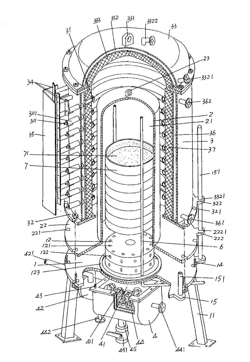
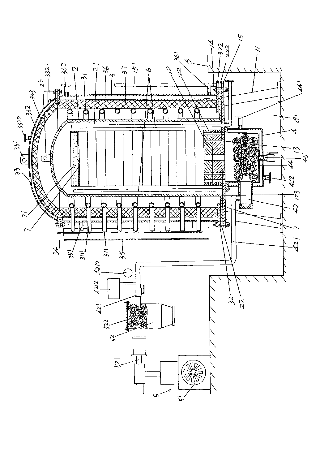
[0022] please see figure 1 and figure 2 , a furnace platform 1 is given, and the furnace platform 1 has a group of vacating feet 11 for vacating the furnace platform 1 on the floor of the place of use, that is to say, the furnace platform 1 and the floor are kept At a certain distance, a group of furnace platform through holes 13 ( figure 2 shown), a pair of bases 12 are stacked at the position cor...


PUM


Abstract

The invention discloses a siphon-type degreasing furnace and belongs to the field of degreasing devices of powder metallurgy injection molding parts. The siphon-type degreasing furnace comprises a furnace pipe platform, a furnace pipe, a furnace body, a trap, a vacuumizing mechanism and a protective gas introducing tube, wherein the center of one side of the furnace pipe platform is provided witha base; the furnace pipe is arranged on the furnace pipe platform; the furnace body is sheathed at the exterior of the furnace pipe; a group of electric heating rods are laid in the inner wall of thefurnace body; the trap is fixed in the center on one side of the furnace pipe platform; the vacuumizing mechanism is arranged on one side of the furnace body; one end of the protective gas introducing tube extends into a furnace pipe cavity; the other end of the protective gas introducing tube is connected with a protective gas source device; the edge position of the circumstance direction of thefurnace pipe platform is provided with one group of locking buckles; the outer wall of the bottom of the furnace pipe is provided with a coordination plate; the outer wall of the bottom of the furnace body is provided with a fixed flange plate; the edge position of the furnace pipe platform is provided with a first guide rod seat fixedly provided with a guide rod; the edge position of the coordination plate is provided with a second guide rod seat; and the edge position of the fixed flange plate is provided with a third guide rod seat. The siphon-type degreasing furnace has the advantages of improving the degreasing speed, being convenient to replace and maintain and being quick and accurate to assemble.

Description

technical field [0001] The invention belongs to the technical field of degreasing devices for powder metallurgy injection molding parts, and in particular relates to a siphon type degreasing furnace. Background technique [0002] Metal injection molding technology (Metal Injection Molding, referred to as MIM) is a technology that integrates plastic molding technology, polymer chemistry, powder metallurgy technology, and metal materials. Products with complex shapes can be sintered to manufacture structural parts with high density, high precision and three-dimensional complex shapes. This technology was first invented in the last century (1973) by Parmatech Corporation of California, USA, and was widely used in Europe, America and Japan in the early 1980s. This technology has the advantages of fewer process steps, no cutting or a small amount of cutting and high economic benefits, and can overcome the traditional powder metallurgy process of low density, uneven material, poo...

Claims


Application Information

Patent Timeline
Patent Type & Authority Patents(China)
IPC IPC(8): B22F3/22B22F1/00
Inventor 姬祖春顾晓明顾祖良
Owner 宝得粉末注射成形(常熟)有限公司
Why Eureka
Try Eureka