Elastic vibration-reduction ballast bed system

A kind of ballast bed and elasticity technology, applied in the field of elastic vibration damping ballast bed system, can solve the problems of system stiffness and quality restriction, lengthened construction period, and many construction contents, etc., and achieves the effect of strong anti-overload capability and increased lateral stability.

Inactive Publication Date: 2012-07-04
河北金擘机电科技有限公司 +1
View PDF6 Cites 18 Cited by
  • Summary
  • Abstract
  • Description
  • Claims
  • Application Information

AI Technical Summary

Problems solved by technology

However, the steel spring floating slab track bed also has some shortcomings: (1) In order to achieve the designed vibration isolation effect, the concrete floating slab is bulky, heavy, and expensive, resulting in high engineering costs, and can only be used for special The required vibration reduction section cannot be promoted across the board; (2) The construction content is many, the process is complicated, and the cycle is long; (3) The damping ratio is a fixed value, which cannot meet the different requirements for the damping ratio of the resonance area and the vibration isolation work area at the same time
However, in practice, the stiffness and mass of the system are subject to certain constraints and cannot be arbitrarily reduced or increased
If the rigidity is reduced, the vertical deformation of the rail will be too large, which will reduce the lateral stability of the system and affect the driving safety; and the mass is limited by the structure and space, so it cannot be too large, such as the "Cologne egg" and elastic boots. , the vibration quality has been fixed and cannot be changed; for the steel spring floating slab ballast bed vibration damping system, although the vibration isolation effect can be improved to a certain extent by simply increasing the weight of the concrete floating slab, it will lead to excessive structural size. A series of problems such as large size, substantial increase in cost, and lengthened construction period make the economy worse
[0006] Therefore, the existing rail vibration reduction measures are difficult to achieve for the low-cost, relatively simple construction process, and the 15-40dB mid-to-high-end vibration reduction requirements that are suitable for full-line promotion.

Method used


Image

  • Elastic vibration-reduction ballast bed system
  • Elastic vibration-reduction ballast bed system
  • Elastic vibration-reduction ballast bed system

Examples


Embodiment 1

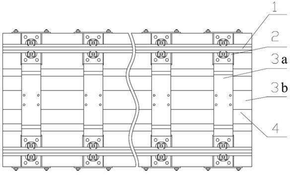
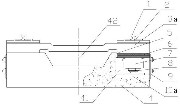
[0058] figure 2 As shown, the concrete ballast bed 4 is formed by pouring on site, and grooves 41 are poured symmetrically in the transverse direction, and drainage ditches 42 are poured in the middle. Connecting bolts are pre-embedded on the lateral end surfaces of the lateral grooves of the concrete ballast bed 4, and the protective cover plate 9 is connected with the concrete ballast bed 4 through the pre-embedded connecting bolts to form a closed space to prevent impurities such as dust and rainwater from entering the grooves.

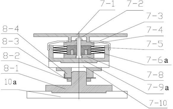
[0059] image 3As shown, there is an elastic gasket 7-10 at the bottom of the low-frequency vibration isolator 7, and the vibration isolator sleeve 7-9a is connected with the elastic gasket 7-10 through a concave-convex structure; the positive and negative stiffness of the vibration isolator sleeve 7-9a are placed Parallel elastic elements, positive and negative stiffness parallel elastic elements are composed of disc spring 7-5 and metal rubber-...

Embodiment 2

[0068] Such as Figure 4 As shown, this embodiment is basically the same as Embodiment 1, the difference is that the positive stiffness elastic element in the low-frequency vibration isolator 7 is composed of a helical steel spring 7-7 and a metal rubber elastic element 7-6b connected in parallel, and the helical steel spring 7-7 sets On the outer side of the metal rubber elastic element 7-6b, the two together provide positive stiffness for the low frequency vibration isolator. The metal rubber elastic element 7-6b can also provide certain damping for the low-frequency vibration isolator, so that the low-frequency vibration isolator has variable damping characteristics, and at the same time meets the different requirements of the vibration isolator for damping in the resonance region and the vibration isolation region. In addition, the helical steel spring and the metal rubber elastic element can also be armored to form an independent positive stiffness elastic element.

[00...

Embodiment 3

[0071] Such as Figure 5 As shown, this embodiment is basically the same as Embodiment 1, the difference is that the low-frequency vibration isolator 7 adopts a separate positive stiffness elastic element, and the positive stiffness elastic element is a helical steel spring 7-7. The lower bottom plate 7-8 is connected with the grooved vibration isolator sleeve 7-9b through a concave-convex structure, and the grooved vibration isolator sleeve 7-9b is filled with damping fluid 7-11a.


PUM


Abstract

The invention discloses an elastic vibration-reduction ballast bed system, which comprises a concrete ballast bed and a low-frequency vibration isolator installed in the concrete ballast bed. An elastic mechanism in the low-frequency vibration isolator consists of a positive stiffness elastic element made of metal rubber or the positive stiffness elastic element and a negative stiffness elastic element which are connected in parallel. The positive stiffness elastic element is a disc spring, a spiral spring, the metal rubber, a metal rubber-spring armour, a metal rubber-lead core composite spring or any series-parallel combination of the disc spring, the spiral spring, the metal rubber, the metal rubber-spring armour and the metal rubber-lead core composite spring. The negative stiffness elastic element is a disc spring or a diaphragm spring. The elastic vibration-reduction ballast bed system can meet requirements of middle-high-grade vibration reduction and has a simple structure. The site construction process is simple and convenient, and consumed materials of the ballast bed are relatively reduced. Therefore, the elastic vibration-reduction ballast bed system is low in construction cost and suitable for popularization and application in the whole line.

Description

technical field [0001] The invention belongs to a railway track bed, and in particular relates to a track structure of a railway, specifically an elastic damping track bed system used in railways, high-speed railways, urban railways, subways and elevated light rails. Background technique [0002] In recent years, my country is gradually increasing the investment and construction of high-speed railways and urban rail transit (subway, urban railway, elevated light rail, etc.). High-speed railways shorten the travel time of passengers, and are energy-saving, environmentally friendly, safe and reliable. In big cities with traffic congestion, convenient and fast urban rail transit is more and more popular and has become the first choice for people to travel. Subsequently, the vibration and noise problems caused by rail transit that affect the surrounding environment of the line and residents' life and health have attracted more and more attention from researchers at home and a...

Claims


Application Information

Patent Timeline
Patent Type & Authority Applications(China)
IPC IPC(8): E01B1/00E01B19/00
Inventor 白鸿柏路纯红张培林李冬伟
Owner 河北金擘机电科技有限公司
Why Eureka
Try Eureka