
Hydraulic Pneumatic Compound Piling Hammer

A hydraulic pneumatic, piling hammer technology, applied in the direction of sheet pile wall, building, foundation structure engineering, etc., can solve the problems that cannot meet the requirements of modern foundation construction, and achieve small radial installation size, avoid pipeline connection, and no oil fume pollution effect

Active Publication Date: 2016-04-20
上海工程机械厂有限公司
View PDF6 Cites 0 Cited by
  • Summary
  • Abstract
  • Description
  • Claims
  • Application Information

AI Technical Summary

Problems solved by technology

However, neither the existing diesel pile hammer nor the general hydraulic pile hammer can meet the requirements of modern foundation construction.

Method used

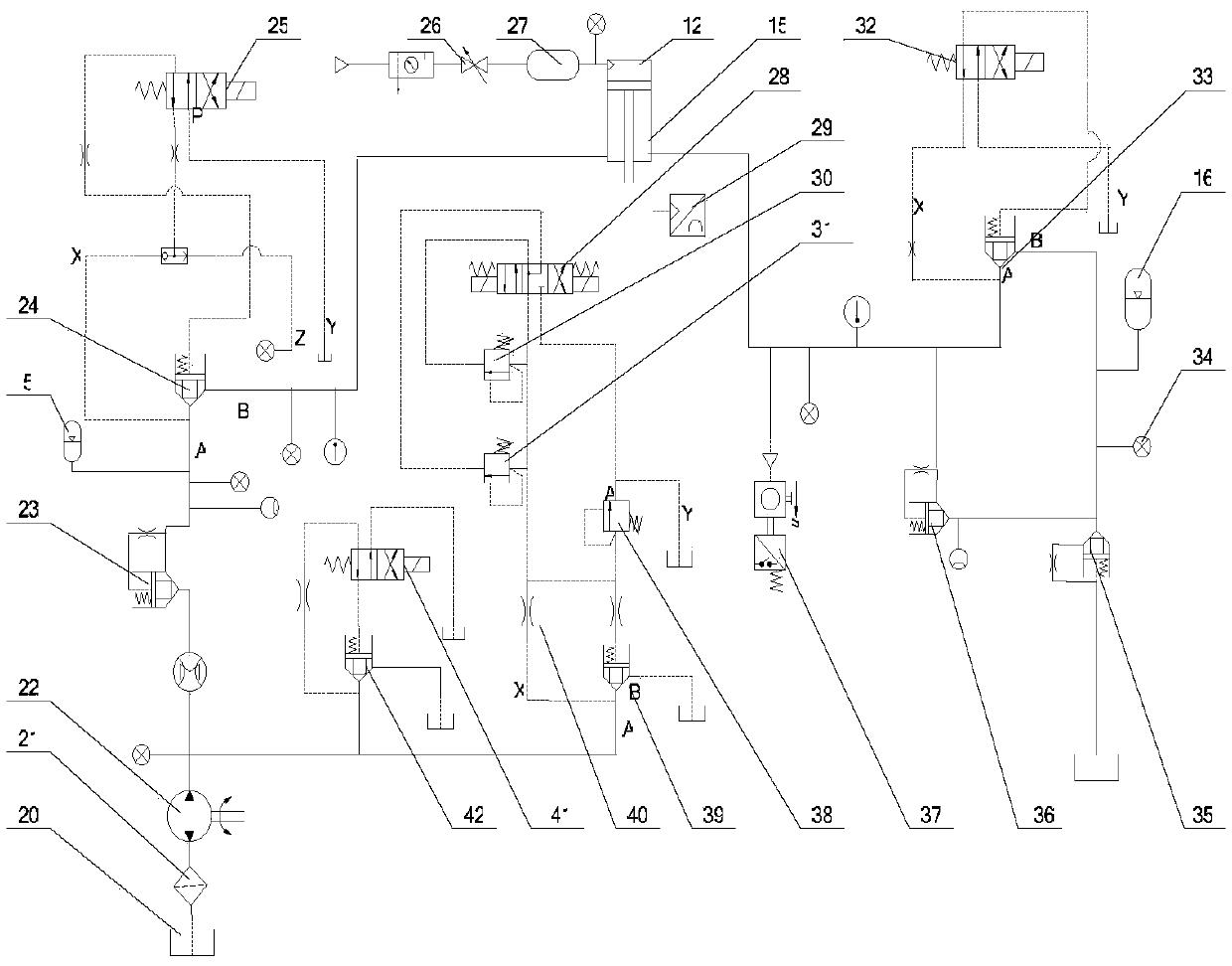
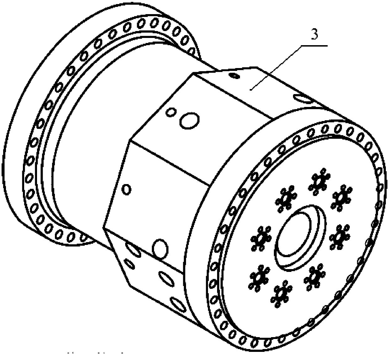

Image

  • Hydraulic Pneumatic Compound Piling Hammer
  • Hydraulic Pneumatic Compound Piling Hammer
  • Hydraulic Pneumatic Compound Piling Hammer

Examples


Embodiment Construction

[0024] The present invention will be further described below in conjunction with the embodiments described in the accompanying drawings.

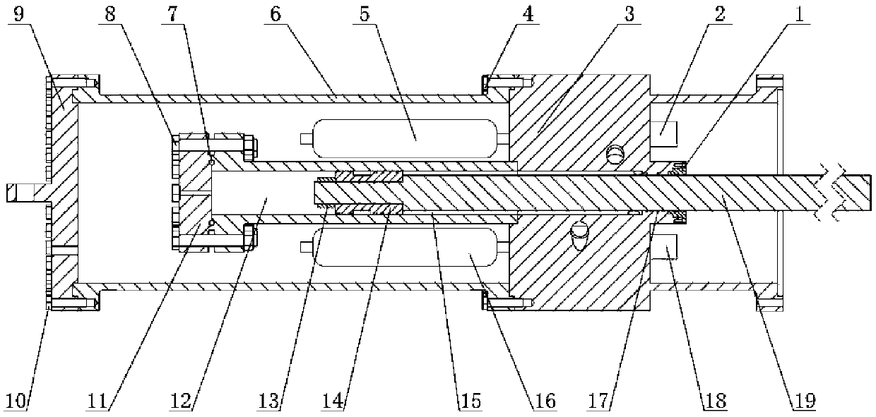
[0025] figure 1It is a structural schematic diagram of the main part of an embodiment of the present invention. As shown in the figure, the hydraulic-pneumatic composite piling hammer of the present invention structurally includes a piston rod end cover assembly 1, an oil supply valve assembly 2, an integrated combined valve block 3, hexagon socket bolt A4, a high-pressure accumulator assembly 5, and a cylinder Body 6, seal 7, hexagon socket bolt B8, ring top cover 9, socket bolt C10, cylinder end cover 11, cylinder 12, lock nut 13, piston 14, hydraulic cylinder (integrated hydraulic pneumatic composite control cylinder) 15 , Low pressure accumulator assembly 16, piston rod seal assembly 17, oil return valve assembly 18, piston rod 19. Wherein, the hydraulic cylinder 15, the piston rod 19, the piston 14, and the cylinder 12 structurally f...


PUM


Abstract

The invention discloses a hydraulic pneumatic composite pile hammer. A hydraulic cylinder, a piston rod, a piston and an air cylinder form an integrated hydraulic pneumatic composite control cylinder, and the reciprocating motion and hammering of the pile hammer are realized by hydraulic force, aerodynamic force and the gravity of the piston rod. Integrated combination valves, high-pressure accumulators and low-pressure accumulators are connected by a pipeline-free and integrated connection mode, and the high-pressure accumulators and the low-pressure accumulators are integrated on the integrated combination valves, so that large-flow quick supply and quick discharge can be realized. In the air cylinder, compressed air is used as a working medium, air is compressed and expanded once in the air cylinder in a working cycle, and a hammer body can descend quickly by using the energy of the air. Cartridge valve banks are subjected to large-flow control by solenoid directional valves. The low-pressure accumulators fill oil into a hydraulic cylinder through the cartridge valve banks and absorb vibration for buffering. Due to the adoption of a fully-closed structure and a piston rod guide mechanism, an inclined pile is hammered and underwater operation is realized.

Description

technical field [0001] The invention belongs to the field of mechanical engineering and civil engineering engineering machinery piling machinery, mechanical parts and transmission devices, and in particular relates to a mechanical structure and equipment of a hydraulic-pneumatic composite piling hammer. Background technique [0002] The origin of piles can be traced back to the Hemudu people who used wooden piles as the foundation to build houses in Hemudu more than 7,000 years ago. Since modern times, people have invented various piling machinery for piling. There are many types of mechanical piling hammers commonly used in building foundation construction, such as diesel piling hammers and hydraulic piling hammers. Due to the disadvantages of high energy consumption, high noise and pollution, the traditional drop hammer diesel piling hammer has been restricted in many countries and regions. Hydraulic pile hammer technology originated in the 1960s. The hydraulic piling h...

Claims


Application Information

Patent Timeline
Patent Type & Authority Patents(China)
IPC IPC(8): E02D7/14
Inventor 訚耀保俞凌霏张慧颖陶雷张国强
Owner 上海工程机械厂有限公司
Learn More