
Combined-type hydraulic chuck for tunnel drilling rig

A technology for hydraulic chucks and tunnel drilling rigs, which is applied to drill pipes, drill pipes, and drilling equipment. It can solve the problems of small holding force, low degree of automation, and cumbersome use and operation, and achieve light weight, small volume, and easy transportation. Effect

Inactive Publication Date: 2012-07-04
XIAN ZHONGZHI HUIZE PHOTOELECTRIC TECH
View PDF0 Cites 1 Cited by
  • Summary
  • Abstract
  • Description
  • Claims
  • Application Information

AI Technical Summary

Problems solved by technology

The traditional drill pipe clamping device of tunnel drilling rig is mechanical, with small holding force, no force-increasing effect, easy to fall off, and the chuck has complex structure, cumbersome operation, high labor intensity, low efficiency and low degree of automation

Method used


Image

  • Combined-type hydraulic chuck for tunnel drilling rig
  • Combined-type hydraulic chuck for tunnel drilling rig

Examples


Embodiment Construction

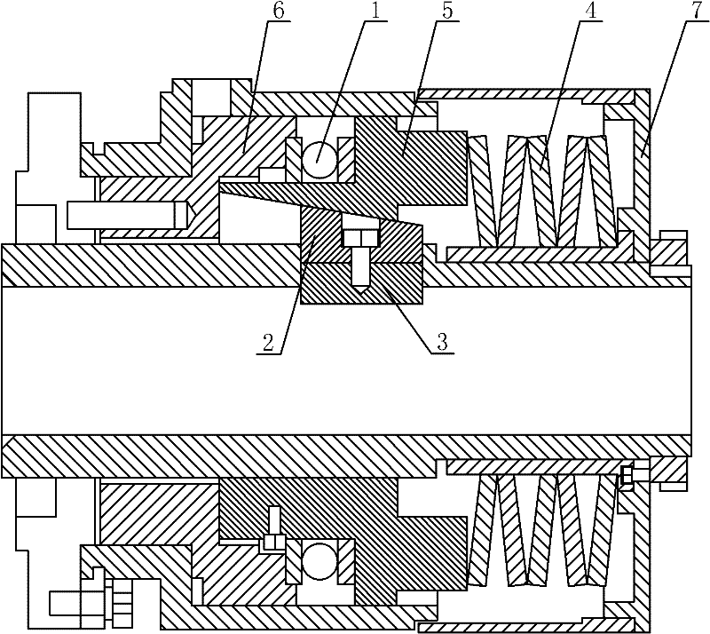
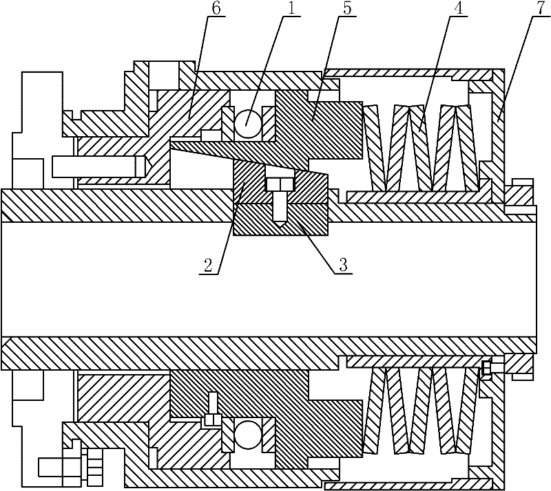
[0019] Such as figure 1 The shown combined hydraulic chuck for a tunnel drilling rig includes slips 3 on which an inner slope mechanism 2 is installed, and an outer slope mechanism 5 is slidingly installed on the outer side of the inner slope mechanism 2. A bearing 1 is arranged between one end of the ramp mechanism 5 and the stop disc one 6 , and a spring 4 is arranged between the other end of the outer ramp mechanism 5 and the stop disc two 7 .

[0020] Such as figure 1 As shown, the inclination angle of the inner bevel mechanism 2 is less than 10°, the inclination angles of the inner bevel mechanism 2 and the outer bevel mechanism 5 are equal, the bearing 1 is a thrust bearing, and the spring 4 is a butterfly spring. The inner slope mechanism 2 is installed on the slips 3 through screws.

[0021] The working process of the combined hydraulic chuck for the tunnel drilling rig of the present invention is as follows: first, the drill pipe of the tunnel drilling rig is insert...


PUM

PropertyMeasurementUnit
Slope angleaaaaaaaaaa

Abstract

The invention discloses a combined-type hydraulic chuck for a tunnel drilling rig, wherein the combined-type hydraulic chuck comprises a slip, wherein an inner inclined surface mechanism is installed on the slip; an outer inclined mechanism is slidingly installed at the outer side of the inner inclined surface; a bearing is arranged between one end of the outer inclined surface mechanism and a blocking plate 1; and a spring is arranged between the other end of the outer inclined mechanism and a blocking plate 2. The combined-type hydraulic chuck for the tunnel drilling rig provided by the invention has the following characteristics of simple structure, convenience in using, high automation degree, small volume, light weight, great convenience in transportation, good clamping effect and low labor intensity.

Description

technical field [0001] The invention belongs to the technical field of coal mine machinery and relates to a chuck, in particular to a combined hydraulic chuck for a tunnel drilling machine. Background technique [0002] At present, my country's coal mining speed is growing rapidly. With the gradual increase of coal mining depth, the risk of coal mine gas outburst and explosion is also increasing, and coal mine gas outburst and explosion accidents often occur. Putting it into the atmosphere will not only damage the atmospheric environment, but also does not meet the requirements of energy saving and emission reduction. Therefore, the method of drainage and comprehensive utilization of mine gas has been adopted at home and abroad to solve this problem. However, mines put forward higher requirements and a wider range of use for drilling rigs, which are indispensable in the safety measures for preventing gas accidents. Long-distance drilling under high-gas complex geological con...

Claims


Application Information

Patent Timeline
IPC IPC(8): E21B19/10
Inventor 江新兵
Owner XIAN ZHONGZHI HUIZE PHOTOELECTRIC TECH
Learn More