Dynamic control system and control method for downhole directional power drilling tool face

A technology of control system and power drilling tool, which is applied in the direction of automatic drilling control system, drilling equipment, earthwork drilling and production, etc. It can solve problems such as failure of wellbore trajectory control, drift of drilling tool face, and hysteresis of applied drilling pressure, etc., to achieve Improve wellbore purification, reduce drilling complex accidents, and achieve effective transmission

Active Publication Date: 2012-07-04
CHINA NAT OFFSHORE OIL CORP +1
View PDF8 Cites 27 Cited by
  • Summary
  • Abstract
  • Description
  • Claims
  • Application Information

AI Technical Summary

Problems solved by technology

[0002] In conventional drilling operations, the vertical well section and the stabilizing section are usually drilled by top drive or rotary drilling, and if the steering drilling section uses the downhole angled deflection power drilling tool, the sliding drilling method is usually used. Under the conditions of adjustment, stratum lithology change, power drilling tool wear and other conditions, it is easy to cause drilling tool face drift, resulting in failure of wellbore trajectory control and other problems
Faced with this situation, the usual practice is to reset the tool face by stopping drilling and lifting the drilling tool after the downhole tool face has drifted, which will affect the operating timeliness
At the same time, in the sliding drilling process of conventional steerable drilling tools, because the drilling tool cannot rotate, the application of drilling pressure is delayed, the wellbore cleaning is difficult, and it is easy to cause problems such as low operating efficiency and complicated procedures.

Method used


Image

  • Dynamic control system and control method for downhole directional power drilling tool face
  • Dynamic control system and control method for downhole directional power drilling tool face
  • Dynamic control system and control method for downhole directional power drilling tool face

Examples


Embodiment Construction

[0013] The present invention will be described in detail below with reference to the drawings and embodiments.

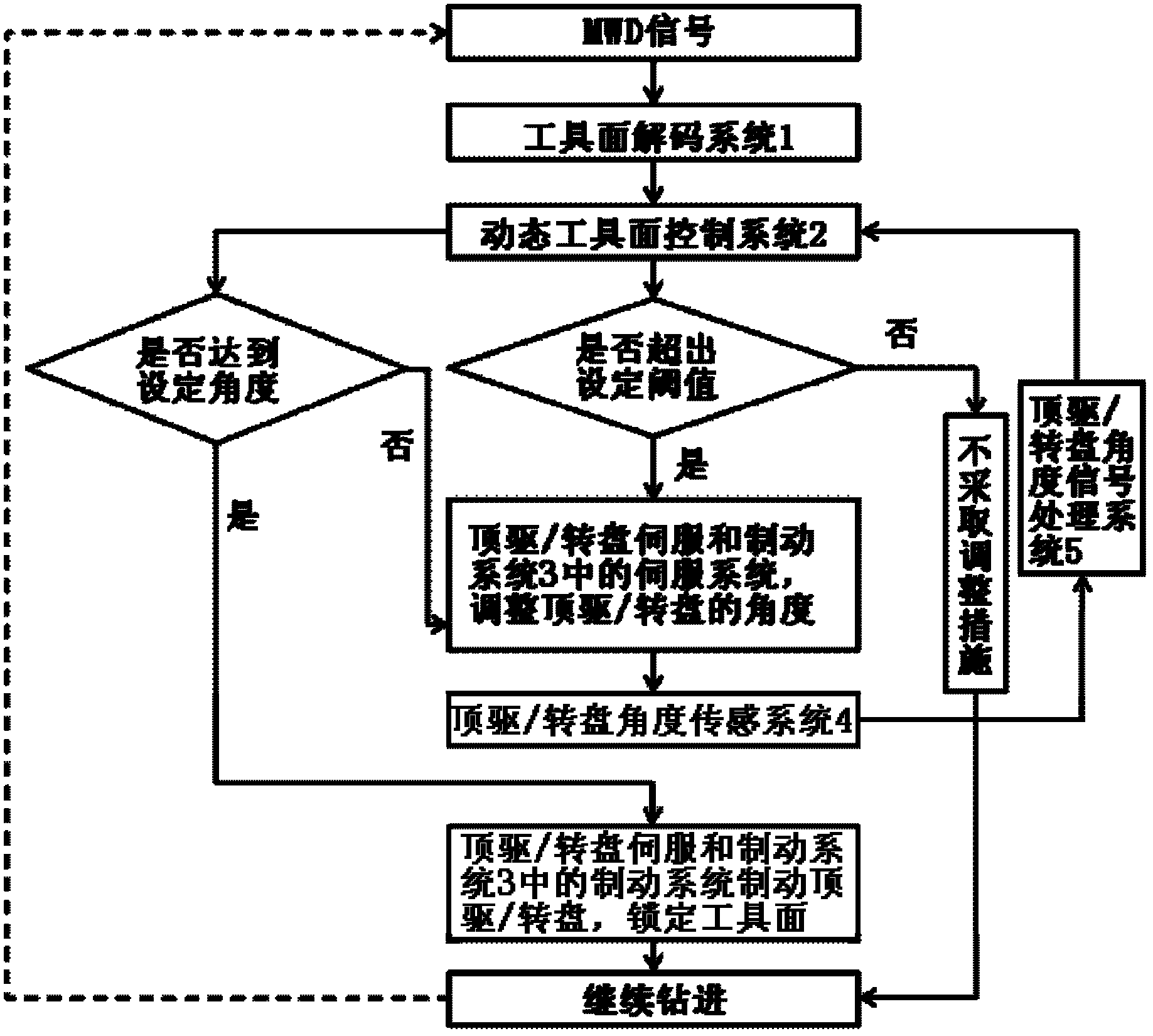
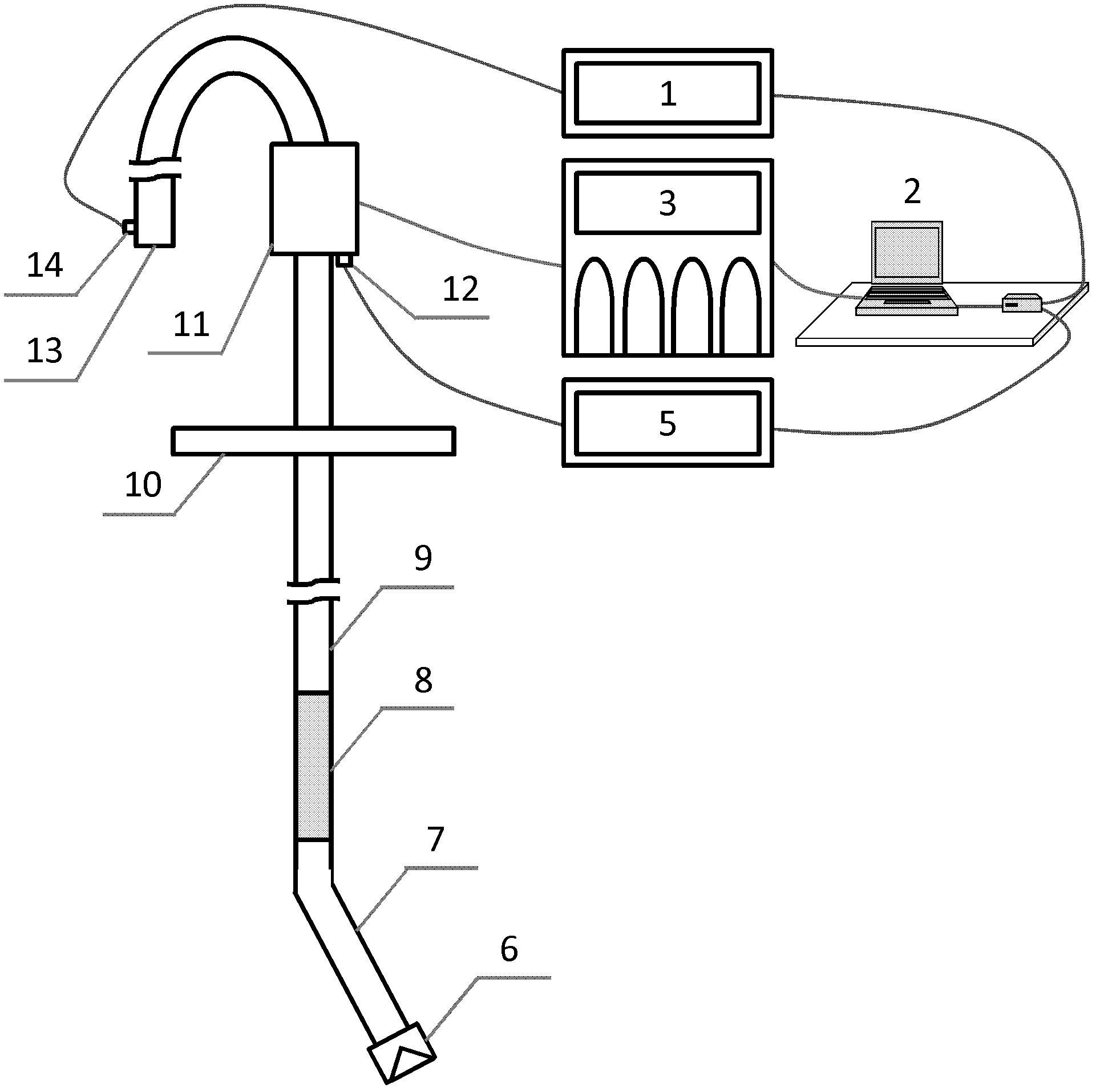
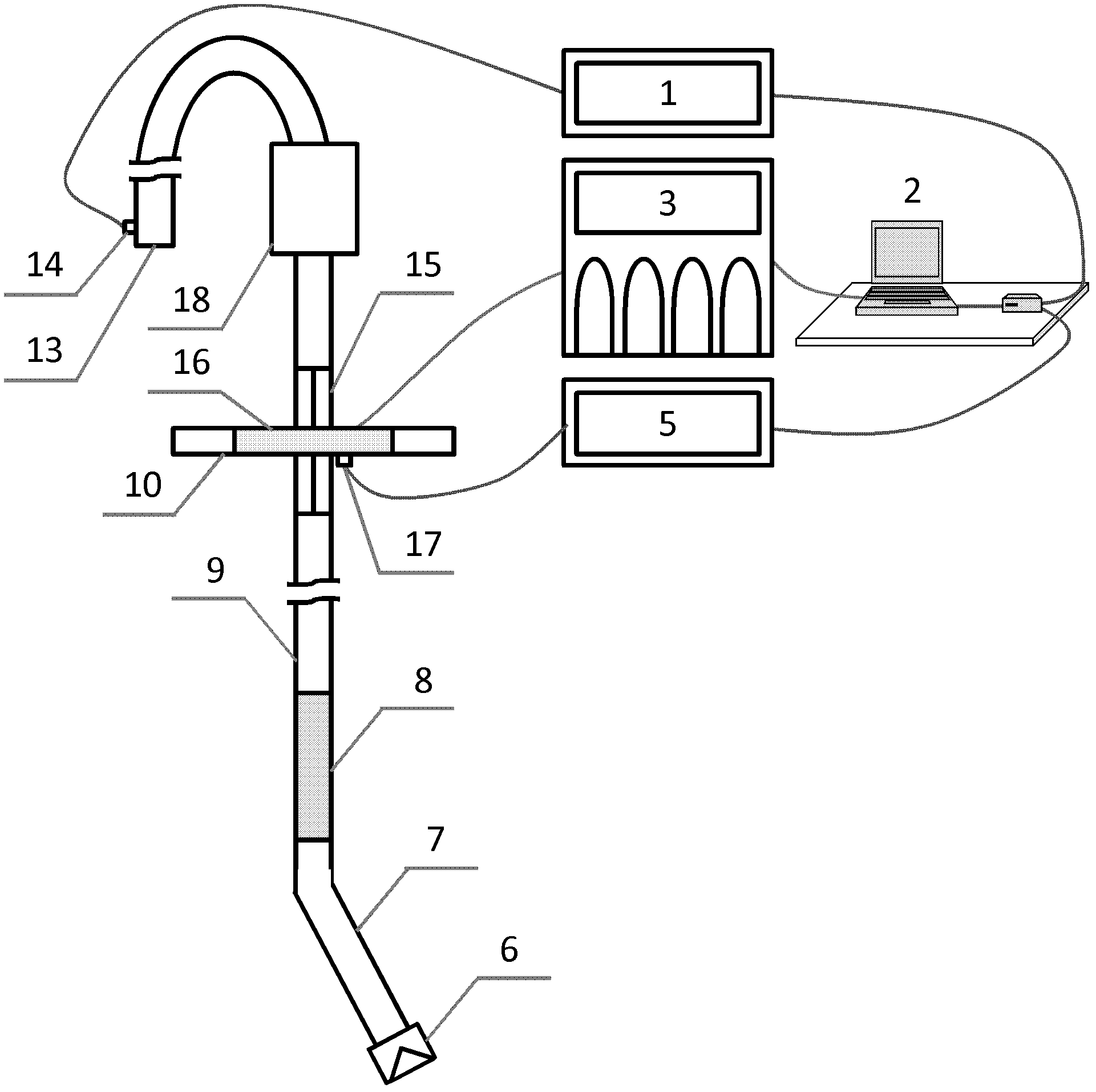
[0014] Such as figure 1 As shown, the control system of the present invention is suitable for the case where the drilling power system is a top drive and the drilling power system is a turntable. The control system of the present invention includes a set of tool surface decoding system 1, a set of dynamic tool surface control system 2, a set of top drive / turntable servo and brake system 3, a set of top drive / turntable angle sensing system 4 and a set of top Drive / turntable angle signal processing system 5. The input end of the tool face decoding system 1 is connected to the pressure signal sensor of the MWD (Measure While Drilling) system in the drilling system, and the output end is connected to the dynamic tool face control system 2. The dynamic tool face control system 2 is preset in the monitoring computer , The output end of the dynamic tool surface control syste...


PUM


Abstract

The invention relates to a dynamic control system and a control method for a downhole directional power drilling tool face. The dynamic control system is characterized in that the dynamic control system comprises a set of tool face decoding system, a set of dynamic tool face control system, a set of top drive/turntable servo and brake system, a set of top drive/turntable angle sensing system and a set of top drive/turntable angle signal processing system; and the input end of the tool face decoding system is connected with the pressure signal sensor of a measurement while drilling (MWD) system in a well drilling system, the output end of the tool face decoding system is connected with the dynamic tool face control system, the dynamic tool face control system is preset in a monitoring computer, the output end of the dynamic tool face control system is connected with the top drive/turntable servo and brake system, the top drive/turntable servo and brake system is connected with a top drive/turntable and the top drive/turntable angle sensing system, the output end of the top drive/turntable angle sensing system is connected with the top drive/turntable angle signal processing system, and the output end of the top drive/turntable angle signal processing system is connected with the dynamic tool face control system. The dynamic control system and the control method can be widely used for the dynamic adjustment control of the downhole directional power drilling tool face.

Description

Technical field [0001] The invention relates to a control system and a control method for controlling tool faces during oil and gas field drilling, in particular to a downhole directional power drilling tool tool face dynamic control system and a control method. Background technique [0002] In the process of conventional drilling operations, the vertical section and the stable section usually use top drive or turntable rotary drilling. If the directional drilling section uses the downhole angle type deflection power drilling tool, the sliding drilling method is usually used. Under conditions such as adjustment, stratum lithology changes, and power drill tool wear, tool face drift is likely to occur, leading to problems such as failure of borehole trajectory control. In the face of this situation, the usual practice is to stop drilling and raise the tool to reset the tool face after the downhole tool face drifts. This will affect the operating timeliness. At the same time, in th...

Claims


Application Information

Patent Timeline
Patent Type & Authority Applications(China)
IPC IPC(8): E21B44/00
Inventor 张凤久何保生周建良曹砚锋李汉兴武广瑷张春阳杨立平范白涛
Owner CHINA NAT OFFSHORE OIL CORP
Why Eureka
Try Eureka