Positive pulse device for slurry under shaft

A positive pulse and mud technology, which is used in wellbore/well components, measurement, earth-moving drilling, etc., can solve the problems of well wall damage, slow data transmission speed of mud positive pulse transmission signal, strong erosion effect of parts, etc. Achieve the effect of changing the backhaul response speed, ensuring the data transmission speed, and increasing the pulse rate

Active Publication Date: 2012-07-04
GOALTECH
View PDF7 Cites 14 Cited by
  • Summary
  • Abstract
  • Description
  • Claims
  • Application Information

AI Technical Summary

Problems solved by technology

[0004] 1. The working principle of the mud negative pulse generator is that by opening a relief valve, the mud in the drill string can flow into the annulus of the wellbore through the relief valve and the discharge hole on the drill collar, thereby causing a The mud pressure is reduced, but because the mud negative pulse generator has strong erosion damage to the formation, it will cause relatively serious damage to the well wall, and has a relatively strong erosion effect on parts, and it consumes a lot of power. The structure of the instrument is relatively Complicated, not conducive to assembly, operation, maintenance
[0005] 2. The working principle of the mud continuous wave pulse generator is to use the rotary valve to generate a fixed frequency pressure continuous wave, and encode and decode the information according to the phase shift of the continuous wave, but the mud continuous wave pulse generator also has complex structure and expensive manufacturing cost And other issues
However, due to the slow transmission speed of mud positive pulse transmission signal data, this system is not suitable for transmitting a large number of geological data parameters

Method used


Image

  • Positive pulse device for slurry under shaft
  • Positive pulse device for slurry under shaft
  • Positive pulse device for slurry under shaft

Examples


Embodiment Construction

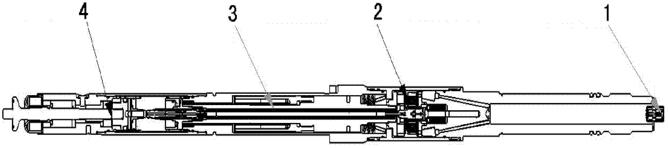
[0019] Such as figure 1 Shown is a schematic structural view of the downhole mud positive pulse device of the present invention. The downhole mud positive pulse device includes four parts: an output terminal 1, a valve body and a generator assembly 2, an intermediate bearing sleeve 3 and a top assembly 4. Sections are connected sequentially. The setting of the output terminal ensures the communication connection between the downhole mud positive pulse device and other instruments, so that the power generated by the generator can be transmitted, and at the same time receive the control signals of other instruments; the control valve mainly controls the opening and closing of the hydraulic circuit of the pulsator. control the reciprocating motion of the lifting rod at the top to realize pulses; the generator mainly provides electric energy for various instruments in the well; the intermediate bearing sleeve assembly is mainly composed of a magnetic shaft, a generator disk and a ...


PUM


Abstract

The invention discloses a positive pulse device for high-speed slurry under a shaft. The positive pulse device comprises an output terminal, a valve body and generator assembly, an intermediate bearing bush and top assembly which are connected sequentially, wherein the top assembly comprises a piston and a spring which are arranged in a shell on the top and a plunger pump and a tilting tray which are arranged at the upper end of the intermediate bearing bush; the plunger pump comprises a plunger pump shell and a plunger positioned in the plunger pump shell; an oil drainage hole is formed in the shell on the top and is positioned on the end part below the shell on the top; and a return spring is arranged between the shell on the top and the piston. In order to overcome the defect of slow data transmission of the conventional pulser, according to the positive pulse device, parts such as the oil drainage hole, the plunger, the tilting tray and the like are improved, namely a slant angle of the tilting tray is improved, the round-trip distance of the piston is shortened, the speed of pulses is improved, and the return spring is arranged between the piston and the pump additionally to change the response speed of the return stroke of the pulser, so that the response speed of the pulser is improved, and the data transmission speed of high-speed pulse interval data formats is ensured.

Description

technical field [0001] The invention belongs to the field of petroleum drilling engineering, and in particular relates to a downhole device for wirelessly measuring well deviation and relevant geological parameters while drilling in petroleum drilling. Background technique [0002] MWD (Measurement While Drilling) and LWD (Logging While Drilling) are the key technologies for completing large-angle and horizontal well drilling, real-time data acquisition, interpretation and on-site decision-making at the well site, and guiding the completion of geosteering drilling. The most important part of the drilling measurement system, the signal is mainly transmitted through the pressure wave of the drilling fluid. The basic principle of mud pulse transmission is that the signal measured by the downhole sensor is coded, and the drive control circuit of the pulser drives the cone valve, rotary valve or rotor of the mud pulser to work, resulting in a interception effect, thereby generati...

Claims


Application Information

Patent Timeline
Patent Type & Authority Applications(China)
IPC IPC(8): E21B47/18
Inventor 倪庆祥孙连奎边卫民熊陵
Owner GOALTECH
Why Eureka
Try Eureka