Drawn cup needle roller bearing having a seal ring and its manufacture method

A technology for stamping outer rings and needle roller bearings, which is applied in the direction of needle roller bearings, roller bearings, rolling contact bearings, etc., can solve the problems that the roundness of the inner diameter of the sealing ring and the required precision such as inner diameter tolerance cannot be produced, and achieve low Increased torque, good dimensional accuracy, and anti-wear effects

Inactive Publication Date: 2014-11-26
NSK LTD
View PDF9 Cites 0 Cited by
  • Summary
  • Abstract
  • Description
  • Claims
  • Application Information

AI Technical Summary

Problems solved by technology

in such as Figure 21 In the drawn cup needle roller bearing 100 described, it is required to control the amount of through-flow oil. On the other hand, in the case of Figure 22 In the drawn cup needle roller bearing 110 described, since the seal ring 114 is cut, there is a problem that the required accuracy such as the roundness of the inner diameter of the seal ring and the dimensional tolerance of the inner diameter cannot be produced.

Method used


Image

  • Drawn cup needle roller bearing having a seal ring and its manufacture method
  • Drawn cup needle roller bearing having a seal ring and its manufacture method
  • Drawn cup needle roller bearing having a seal ring and its manufacture method

Examples


no. 1 example

[0069] (Processing method of the first embodiment)

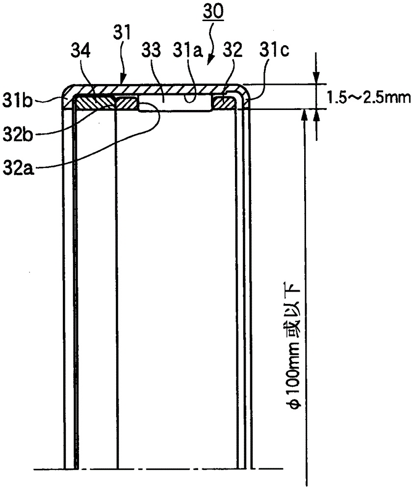
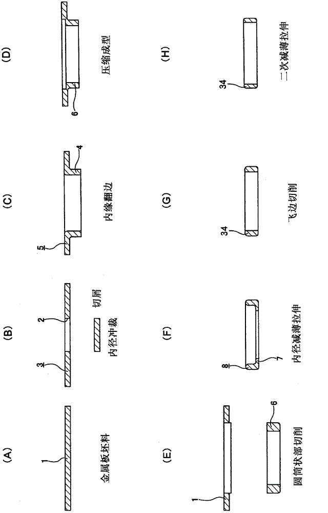
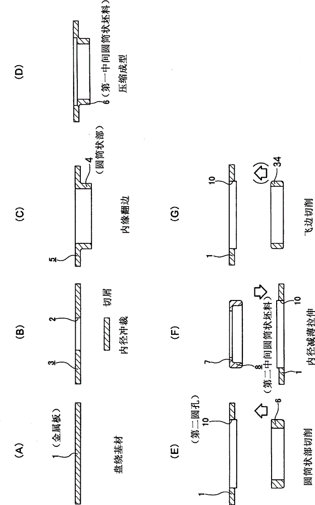
[0070] In the case of this processing method, first, the figure 2 The metal plate 1 shown in (A) as a blank is made of a mild steel plate or a stainless steel plate and is punched to obtain figure 2 (B) The first spare intermediate blank 3 with the circular hole 2 shown. Then, the first spare intermediate blank 3 is subjected to an inner edge flanging process in which the circumference of the circular hole 2 is folded to be at right angles to the above-mentioned metal plate 1 . From the above, we get figure 2 The second spare intermediate blank 5 having the cylindrical portion 4 shown in (C). The volume of the cylindrical portion 4 is larger than the volume of the seal ring to be manufactured. In particular, the length of the cylindrical portion 4 in the axial direction is greater than the length of the seal ring to be manufactured in the axial direction.

[0071] For the cylindrical portion 4 of the above-mentioned ...

no. 2 example

[0080] (The processing method of the second embodiment)

[0081] Figure 3-7 The processing method of the second embodiment is shown. In this case, by sequentially executing the image 3 In the steps shown in (A)→(G), the metal plate 1 is processed into the seal ring 34 . This process is substantially the same as that of the processing method of the first embodiment. In addition, in the case of this example, you can also execute the above-mentioned figure 2 The secondary thinning and stretching process shown in (H). This example is characterized in that, as the above-mentioned metal plate 1, a long metal plate that is sent out from an unshown unwinder and wound up on a not-shown winder is used as the above-mentioned metal plate 1, and the above-mentioned image 3 Steps shown in (A)→(G). That is, in synchronization with the progress of the processing, the above-mentioned elongated metal plate 1 is intermittently sent out at a pitch (interval / pitch=integer) that is balanc...

no. 3 example

[0089] (The processing method of the third embodiment)

[0090] Figure 8 The processing method of the third embodiment is shown. In the case of this example, the Figure 8 In the thinning and stretching process and the back-embedding process shown in (F), the direction in which the second cylindrical intermediate blank 8 is pulled out from the second circular hole 10 of the metal plate 1 and then embedded is relative to the metal plate 1 and the The situation of the processing method of the second embodiment described above is upside down. With reversing the direction, there is no doubt that such Figure 6~7 The structure of the processing device shown varies. Since the structure of other parts is the same as the processing method of the above-mentioned second embodiment, repeated descriptions are omitted.


PUM

PropertyMeasurementUnit
thicknessaaaaaaaaaa
hardnessaaaaaaaaaa

Abstract

A drawn cup needle roller bearing 30 having a seal ring comprises: a shell 31 having a raceway surface 31a on an inner circumferential face and also having inward flange portions 31b, 31c in both end portions; a cage 32 having a plurality of pockets 32a in a circumferential direction and worked by cutting; a plurality of needles 33 retained in the pockets 32a so that the needles freely rotate along the raceway surface 31a; and a seal ring 34, the shape of which is cylindrical, arranged inside the shell 31 between an end face 32b of the cage 32 and the inward flange portion 31b. The seal ring 34 composes a floating seal and is formed by press working. Due to the foregoing, an excellent dimensional accuracy can be provided and a quantity of lubricant passing through the bearing can be controlled.

Description

[0001] This application is a divisional application filed on June 7, 2007 with the international application number PCT / JP2007 / 061550, the national application number 200780021158.5, and the title of the invention "drawn outer ring needle roller bearing with sealing ring and its manufacturing method" . technical field [0002] The present invention relates to a needle roller bearing with a sealing ring and a manufacturing method thereof. Background technique [0003] In the past, sliding bearings (bearings) were often used in automatic transmissions, but drawn cup needle bearings were substituted for bearing bearing burn-in countermeasures and lower torque. [0004] As drawn cup needle roller bearings, known are bearings in which the cross-sectional height of the bearing has been reduced to 1.5 to 2.5 mm, and bearings that have a seal ring in order to achieve the penetration oil volume of the lubricant of the same level as the bearing bush ( For example, refer to Patent Doc...

Claims


Application Information

Patent Timeline
Patent Type & Authority Patents(China)
IPC IPC(8): F16C33/00F16C19/44F16C33/56F16C33/78
CPCB21K1/04F16C19/466B21D53/10F16C33/7809B21K1/05B21K1/761Y10T29/49643Y10T29/49679Y10T29/49703
Inventor 工藤丈洋小林一登堀野庆一大塚清司新藤功
Owner NSK LTD
Why Eureka
Try Eureka