Firework assembling machine

A technology for assembling machines and fireworks, applied in pyrotechnics, offensive equipment, weapon types, etc., can solve problems such as low work efficiency, high labor intensity, and specification errors, so as to avoid cylinder rolling and error accumulation, and reduce maintenance and adjustment workload The effect of small size and shortened processing flow

Inactive Publication Date: 2013-12-11
浏阳市百合机械制造有限公司
View PDF6 Cites 10 Cited by
  • Summary
  • Abstract
  • Description
  • Claims
  • Application Information

AI Technical Summary

Problems solved by technology

At present, this process is done manually in actual production, which has low work efficiency, high labor intensity, large number of workers and high production cost.
[0003] In order to realize the mechanized production of this process, some equipment has been developed, such as: "A Firework Assembly Machine" disclosed in CN2823970, "A Punching and Inserting System for Fireworks Assembly" disclosed in CN102213569A, and "A Firework Assembly System" disclosed in CN202158808U. Fireworks CNC assembly machine", the existing equipment is a single fireworks tube that is cut one by one, and the fireworks tube is pushed horizontally along the direction perpendicular to the central axis of the fireworks tube to the subsequent processing station, and then assembled after gluing, punching and inserting. Arranging, punching and inserting, positioning and assembling fireworks tubes in the process of arranging are more difficult: such as the rolling of the tubes, the accumulation of specification errors in the size of the tubes leads to the change of the processing position, etc. It is difficult to solve many problems, and the maintenance and adjustment workload during operation Large, low production efficiency, it is difficult to be popularized and used in actual production

Method used


Image

  • Firework assembling machine
  • Firework assembling machine
  • Firework assembling machine

Examples


Embodiment Construction

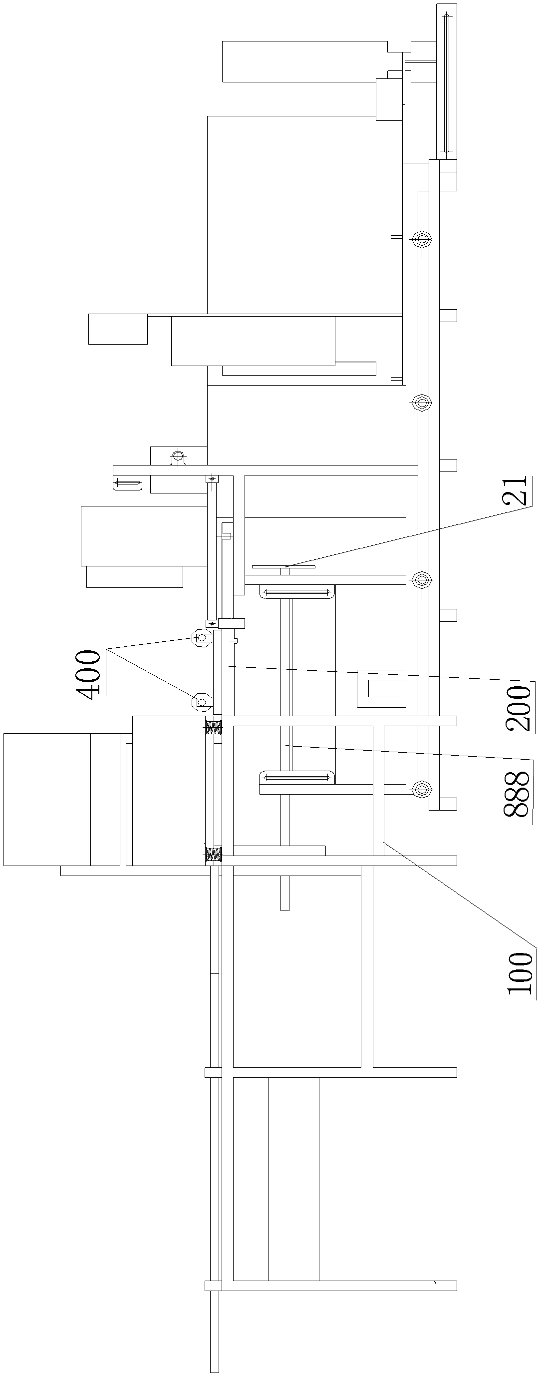
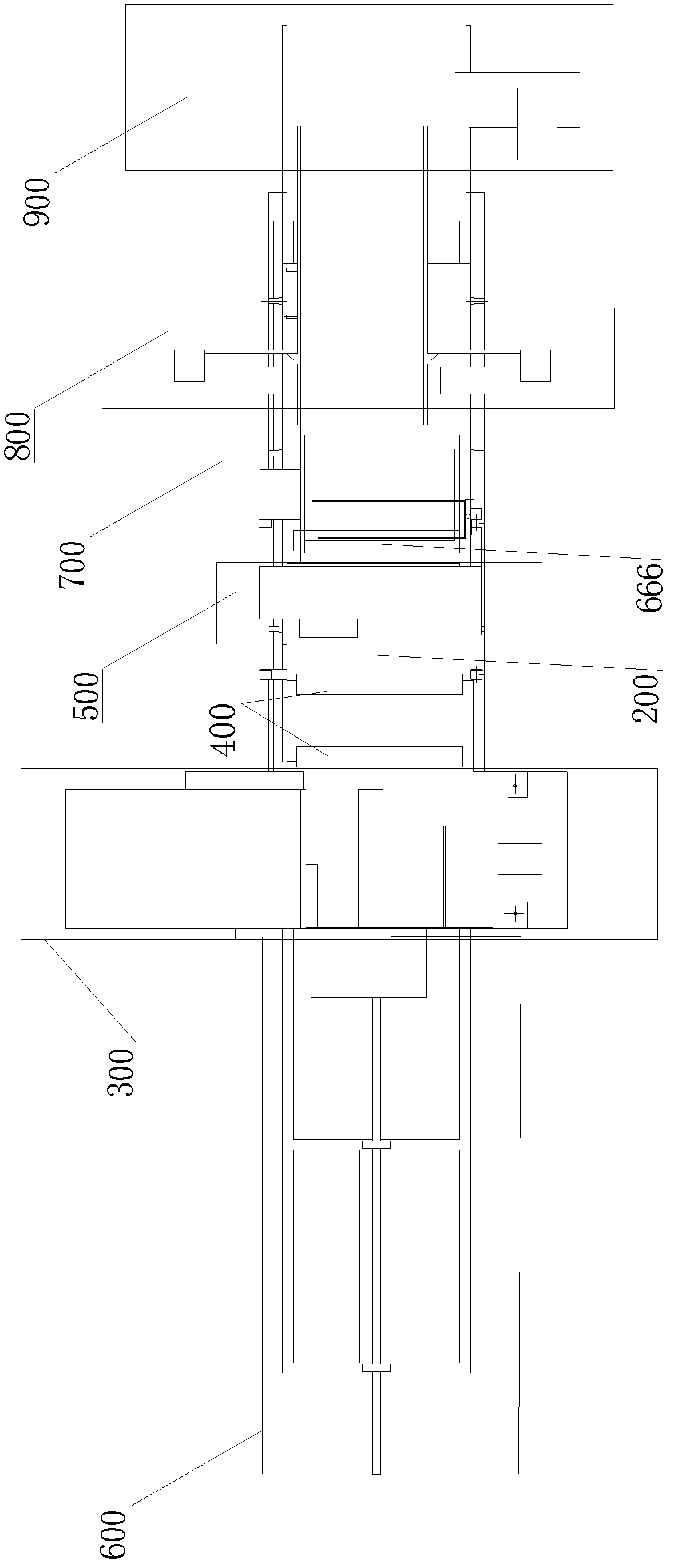
[0058] see Figure 1-2 , reflecting a specific structure of the present invention, the fireworks assembly machine includes a material discharge system 300 , a conveying roller set 400 and a moving insertion system 500 arranged in sequence along the worktable 200 of the main frame 100 , and the rear of the worktable 200 A pusher device 600 is provided to work correspondingly with the blanking and discharging system 300, and a forming system 700 is provided in front of the working table 200 to work correspondingly with the mobile insertion system 500 (here, the "front" and "rear" refer to the advancing direction of the fireworks tube) the front, and vice versa); the discharge system 300 discharges a plurality of fireworks tubes to the work surface 200 at one time according to the required quantity and arranges them in rows; The fireworks tubes are pushed out in a row along the direction parallel to the central axis of the fireworks tube, and are sent to the punching and insertin...


PUM


Abstract

The invention discloses a firework assembling machine. The firework assembling machine comprises a blanking discharge barrel system, a conveying roller group and a moving inserting fuse system which are sequentially arranged along a worktable surface of a main machine frame, wherein a pushing device working corresponding to the blanking discharge barrel system is arranged at the back of the worktable surface, and a forming system working corresponding to the moving inserting fuse system is arranged in front of the worktable surface. The scheme changes horizontal feeding processing through firework barrels one by one in the prior art into longitudinal feeding processing through a plurality of firework barrels in rows, so that processing flow path is shortened, production efficiency is greatly improved, operation is stable, adverse factors like tube body rolling and error accumulation are avoided, work load for maintenance and adjustment in operation is greatly reduced, and the firework assembling machine can perform production continuously without being limited any more. The firework assembling machine solves technical problems and lays good foundation for full automation and mechanized process of fireworks production.

Description

technical field [0001] The invention relates to a firework machine for assembling and molding a plurality of firework tubes. Background technique [0002] In the process of making fireworks, there is a process commonly known as "pot grouping". First, multiple fireworks tubes are glued together to form a row, and holes are drilled into two adjacent tubes to insert the overfire lead, and then the multiple rows of fireworks tubes are glued together. Combine them into a block-shaped whole, and punch holes in the adjacent two rows of fireworks tubes to insert the overfire fuse. At present, this process is all done manually in actual production, which has low work efficiency, high labor intensity, large number of workers, and high production cost. [0003] In order to realize the mechanized production of this process, some equipment has been developed, such as: "A Firework Assembly Machine" disclosed in CN2823970, "A Punching and Inserting System for Fireworks Assembly" disclosed...

Claims


Application Information

Patent Timeline
Patent Type & Authority Patents(China)
IPC IPC(8): F42B4/30
Inventor 周甫国
Owner 浏阳市百合机械制造有限公司
Why Eureka
Try Eureka