Bionic navigation method and navigation positioning system based on remote sensing sky polarization mode patterns

A technology of polarization mode and navigation method, which is applied in navigation, surveying and mapping, navigation, instruments, etc., can solve the problems of blind spots of polarized light in the sky that cannot be effectively monitored and overcome, and the error of measurement results, so as to avoid measurement time error and increase Effectiveness, the effect of expanding the visual field space

Inactive Publication Date: 2012-07-04
PEKING UNIV
View PDF4 Cites 40 Cited by
  • Summary
  • Abstract
  • Description
  • Claims
  • Application Information

AI Technical Summary

Problems solved by technology

At present, the use of sky polarized light to realize remote sensing detection is mainly single-point directional measurement, that is, to measure the distribution information of sky polarized light at a certain altitude angle, and then to measure the sky light in different azimuths multiple times by adjusting the altitude angle of the instrument. The measurement results of each orientation are comprehensively analyzed to obtain the detection results. The above-mentioned single-point directional measurement method has certain limi...

Method used


Image

  • Bionic navigation method and navigation positioning system based on remote sensing sky polarization mode patterns
  • Bionic navigation method and navigation positioning system based on remote sensing sky polarization mode patterns
  • Bionic navigation method and navigation positioning system based on remote sensing sky polarization mode patterns

Examples


Embodiment Construction

[0019] The present invention will be described in detail below in conjunction with the accompanying drawings and embodiments.

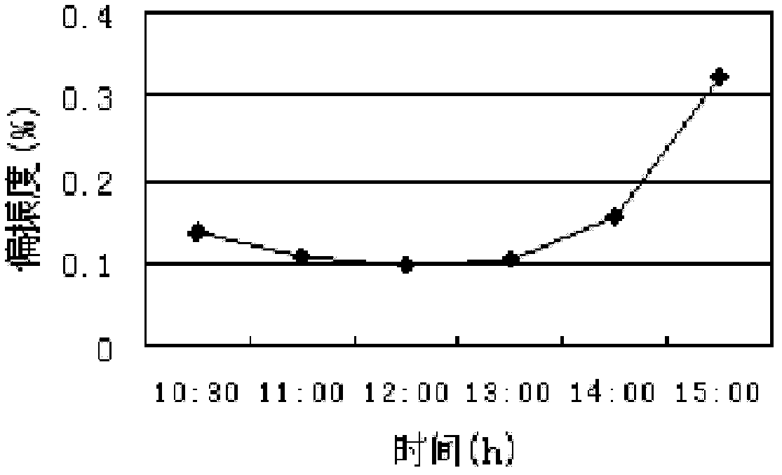
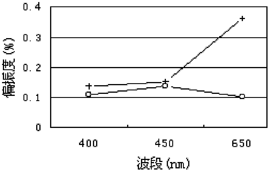
[0020] As we all know, sky light has polarization characteristics due to the scattering of sunlight by atmospheric particles, and the distribution characteristics of sky polarized light are usually expressed by polarization degree and polarization azimuth angle. The target features on the earth's surface and in the atmosphere make the scattered light produce polarization characteristics in the process of reflecting, scattering and transmitting sunlight (electromagnetic radiation), which can be used as an information source for polarization navigation.

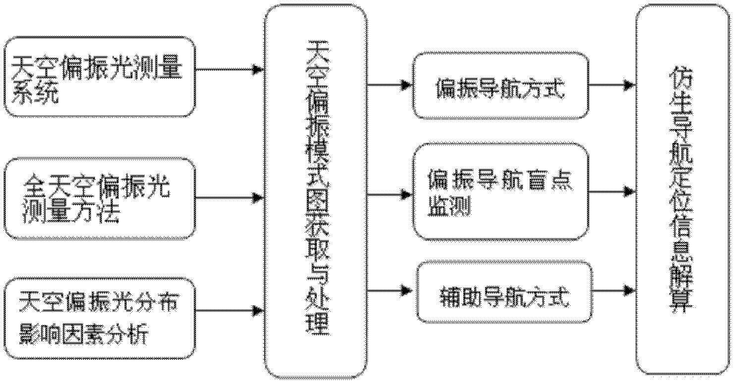
[0021] like figure 1 As shown, the polarized light measurement system of the present invention includes three digital cameras, each digital camera front end is provided with a fisheye lens, each fisheye lens front end is provided with a polarizer and a filter in turn, and the output terminal of each di...


PUM


Abstract

The invention relates to a bionic navigation method and a navigation positioning system based on remote sensing sky polarization mode patterns. The method comprises the following steps: simultaneously measuring three images of light intensity of sky light by adopting a full-sky polarization remote sensing measurement method, and solving a polarization degree and a polarization azimuth angle which describe the polarization state of the sky light, thereby obtaining the remote sensing sky polarization mode patterns; analyzing each influence factor of the polarization degree and polarization azimuth angle in the remote sensing sky polarization mode patterns by adopting a full-sky polarization light measurement method, thereby obtaining the external conditions which are most suitable for polarization navigation; solving the sun azimuth angles at different time by combining celestial navigation theory knowledge, and amending the included angle between the sun meridian and a carrier by utilizing the sun azimuth angles, thereby obtaining a course angle taking geographical north and south as the reference directions; and processing the polarization navigation blind spot by adopting the combined navigation mode of a GPS (global positioning system) navigation mode and a polarization navigation mode. The bionic navigation method and navigation positioning system based on remote sensing sky polarization mode patterns can be widely applied to the measurement and research of navigation positioning under different conditions, and is a special new technology which enables the remote sensing observation image to serve the navigation positioning method and system by utilizing the bionic means.

Description

technical field [0001] The invention relates to a bionic navigation method and a navigation and positioning system, in particular to a bionic navigation method and a navigation and positioning system based on a remote sensing sky polarization pattern map. Background technique [0002] Bionic polarization navigation is an autonomous navigation method in which organisms use the polarization characteristics of light to determine the reference direction, and it is one of the natural navigation methods in nature. This navigation method can avoid some deficiencies of the existing navigation methods, and is combined with inertial navigation, GPS navigation or geomagnetic navigation to become a high-precision navigation method. [0003] Remote sensing is a method of imaging through long distances, or a method of long-distance observation. At present, the use of sky polarized light to realize remote sensing detection is mainly single-point directional measurement, that is, to measur...

Claims


Application Information

Patent Timeline
IPC IPC(8): G01C21/00
Inventor 晏磊关桂霞赵炳爱赵海盟吴太夏陈伟聂志彪高付民吴波施健杨文剑
Owner PEKING UNIV
Why Eureka
Try Eureka