
Self-evaporator liquid level measuring device based on dual-pipe air blowing method
A liquid level measurement device and self-evaporator technology, which is applied in the direction of displaying liquid level indicators through pressure measurement, etc., can solve the problems of complicated management procedures, hazards, and high comprehensive cost of use
- Summary
- Abstract
- Description
- Claims
- Application Information
AI Technical Summary
Problems solved by technology
Method used
Image

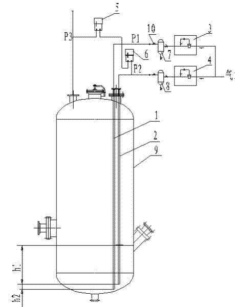
Examples
Embodiment Construction
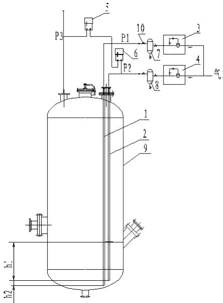
[0053] Embodiments of the present invention: it comprises self-evaporator 9, the first blowing pipe 1, the second blowing pipe 2 are connected with self-evaporator 9, two blowing pipes stretch into the bottom of self-evaporator 9, the first blowing pipe 1 and the second blowing pipe The height difference between the bottom ends of the two air blowing pipes 2 is h2; the pipeline connected with the first air blowing pipe 1 is provided with a first air blower 3, a first isolation tank 7, a first differential pressure transmitter 5, and the first air blower 3. The pipeline connected by the two air blowing pipes 2 is provided with a second air blower 4, a second isolation tank 8, and a second differential pressure transmitter 6; the second air blower 3 and the second air blower 4 are connected to the air source .
[0054] The height h2 between the bottom ends of the first blowing pipe 1 and the second blowing pipe 2 is 200-500 mm. Generally take 300mm.
[0055] The first air blow...
PUM
 Abstract
Description
Claims
Application Information