
Measuring method for pseudo-wind speed of atmosphere in optoelectronic scanning system

A technology of photoelectric scanning and measurement method, which is applied in the direction of fluid velocity measurement, velocity/acceleration/shock measurement, measuring device, etc. It can solve the problem of inaccurate and rigorous atmospheric pseudo-wind velocity measurement method, and achieve a simple and practical method and an accurate calculation process Effect

Inactive Publication Date: 2014-01-22
ANHUI INST OF OPTICS & FINE MECHANICS - CHINESE ACAD OF SCI
View PDF3 Cites 0 Cited by
  • Summary
  • Abstract
  • Description
  • Claims
  • Application Information

AI Technical Summary

Problems solved by technology

[0003] The purpose of the present invention is to provide a measurement method of atmospheric pseudo-wind speed in a photoelectric scanning system, to solve the problem that the measurement method of atmospheric pseudo-wind speed in the prior art is not accurate and rigorous enough

Method used


Image

  • Measuring method for pseudo-wind speed of atmosphere in optoelectronic scanning system
  • Measuring method for pseudo-wind speed of atmosphere in optoelectronic scanning system
  • Measuring method for pseudo-wind speed of atmosphere in optoelectronic scanning system

Examples


Embodiment Construction

[0036] The inventive method comprises the following steps:

[0037] ①. Preparatory conditions: The object S is moving over the ground station, the observation surface is infinite, and the atmospheric wind field plane over the ground station is parallel to the observation surface;

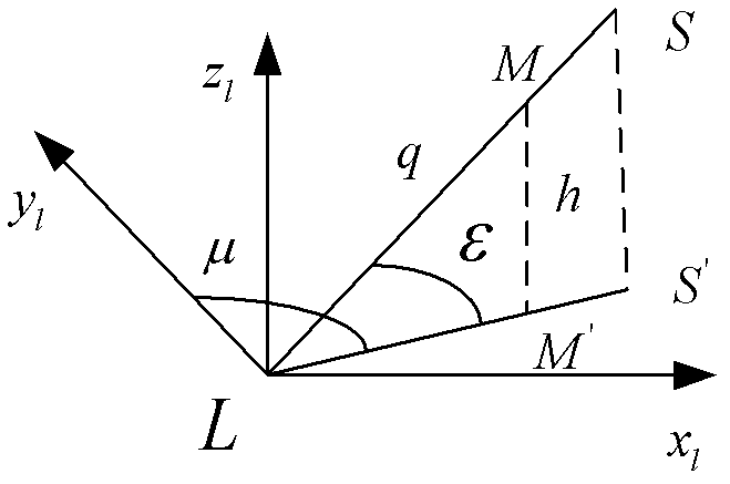
[0038] ②, such as figure 1 As shown, establish a horizontal coordinate system: select an observation point L on the ground station and set it as the origin, and establish a horizontal coordinate system ,That The axis is horizontal to the east, The axis is horizontal to the north, axis vertically upward;

[0039] in the horizontal coordinate system middle, The surface is named as the observation surface, M is a point on the propagation path of the LS beam, and the height from the observation plane is , M' is the projection of M on the observation surface, S' is the projection of S on the observation surface, the state parameters of point S at a certain moment: the veloci...


PUM


Abstract

The invention discloses a measuring method for the pseudo-wind speed of atmosphere in an optoelectronic scanning system and relates to the field of laser atmosphere transmission, in particular to a ground-based optoelectronic scanning system. The measuring method is characterized in that a transformation matrix from a horizontal coordinate system to a scanning coordinate system can be worked out by assuming that an object S moves over a ground station, an observation plane is infinitely larger, and the plane of an atmospheric wind field above the ground station is parallel to the observing plane as long as an azimuth angle and an elevation angle of a moving object in the horizontal coordinate system is known; and the pseudo wind speed of atmosphere at the height can be worked out in combination of the velocity component of the moving object in the horizontal coordinate system and a wind field at a certain height. The measuring method is simple and practical, is accurate and strict in the computing process and has important significance for the computation of the pseudo-wind speed in the optoelectronic scanning system.

Description

technical field [0001] The invention relates to the field of laser atmospheric transmission, in particular to a ground-based photoelectric scanning system, in particular to a method for measuring atmospheric pseudo-wind speed in the photoelectric scanning system. Background technique [0002] In the photoelectric scanning system, the calculation of related parameters needs to use pseudo-wind speed, such as the calculation of thermal distortion parameters, atmospheric turbulence Greenwood frequency and atmospheric turbulence spectrum (intensity, phase, time), etc., so the calculation of atmospheric pseudo-wind speed is very important. Although the concept of atmospheric pseudo-wind velocity in the photoelectric scanning system has existed, there is no unified regulation on the measurement method of atmospheric pseudo-wind velocity in the profession, and the existing measurement method is too simple, and its accuracy and rigor have yet to be verified. Contents of the ...

Claims


Application Information

Patent Timeline
Patent Type & Authority Patents(China)
IPC IPC(8): G01P5/00
Inventor 吴延徽吴毅侯再红靖旭张守川何枫陆茜茜
Owner ANHUI INST OF OPTICS & FINE MECHANICS - CHINESE ACAD OF SCI
Learn More