
High-precision control method for inertia momentum wheel

A technology of inertial momentum and control method, applied in general control system, control/regulation system, linear/angular velocity measurement, etc., can solve the problem of unsatisfactory degree of solution, limited compensation ability of friction nonlinearity, compensation ability involving mechanical Resonance, time-varying parameters, etc.

Inactive Publication Date: 2012-07-04
BEIHANG UNIV
View PDF5 Cites 16 Cited by
  • Summary
  • Abstract
  • Description
  • Claims
  • Application Information

AI Technical Summary

Problems solved by technology

[0004] In addition, the currently widely used disturbance torque compensation method is mainly aimed at the friction torque. Although the research on friction modeling and friction compensation has attracted widespread attention and achieved some results, the solution is far from satisfactory.
Among them, the disadvantage of the compensation method based on the friction model is that the selection of the friction model and the determination of the model parameters are relatively cumbersome, and because the friction torque is a function of the speed, the control effect depends on the quality of the speed signal; the friction compensation method not based on the model Although the principle is simple, the compensation ability for friction nonlinearity is limited, and the improvement of compensation ability involves factors such as mechanical resonance and time-varying parameters; while the friction compensation method of intelligent control does not require a mathematical model of the object, but each has its own advantages and disadvantages , such as the long training time of the neural network, the poor real-time performance of the algorithm, the difficulty in guaranteeing the transient response of the system, the difficulty in obtaining the fuzzy rules, and the unsatisfactory control results, etc.

Method used

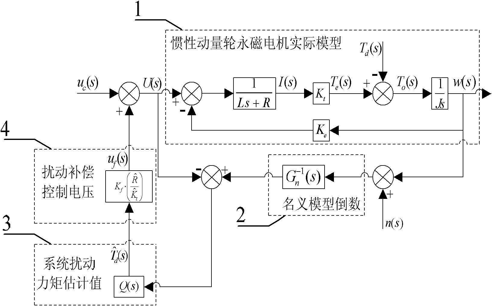
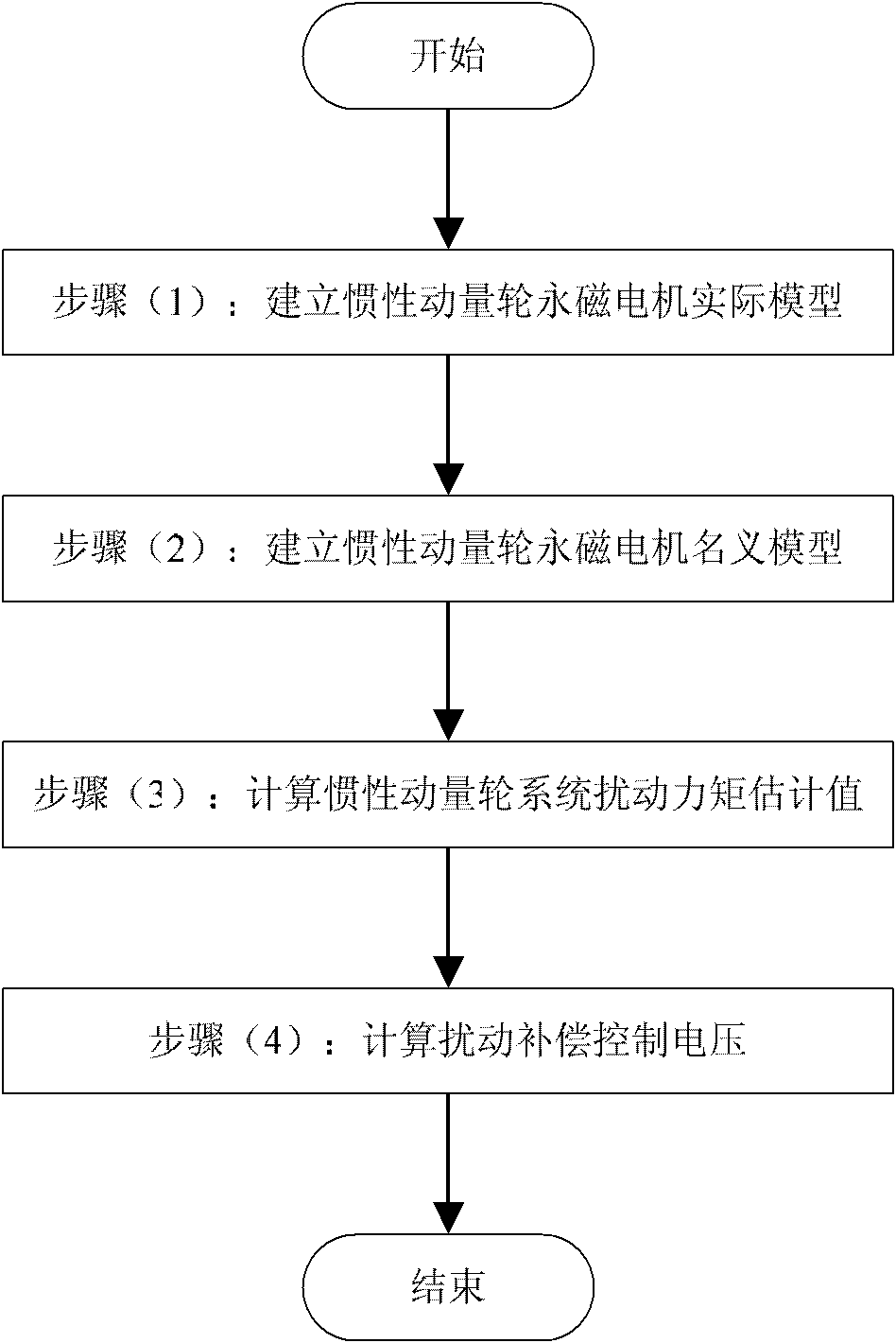

Image

  • High-precision control method for inertia momentum wheel
  • High-precision control method for inertia momentum wheel
  • High-precision control method for inertia momentum wheel

Examples


Embodiment Construction

[0030] Such as figure 2 As shown, a step diagram of a high-precision control method for an inertial momentum wheel in this embodiment, the specific steps are as follows:

[0031](1) Establish the actual model of inertial momentum wheel permanent magnet motor

[0032] According to the principle of permanent magnet motor, there are T e ( s ) = K t I ( s ) E ( s ) = K e ...


PUM


Abstract

The invention relates to a high-precision control method for an inertia momentum wheel. The high-precision control method comprises the following steps that: establishing a practical model and a nominal model of an inertia momentum wheel permanent magnetic motor and synchronously measuring signals of a switch type Hall position sensor, thereby calculating and obtaining a rotating speed value of the present sampling period; taking an internal damping moment, a frictional moment and a bearing noise moment, and the like, of the inertia momentum wheel as total disturbance of a system; unifying an output error of the practical model and the nominal model of the inertia momentum wheel permanent magnetic motor to a control input end; and equivalently estimating the disturbance moment of the system by calculating in real time, thereby obtaining an estimating value of the disturbance moment and introducing an equivalent disturbance compensation control voltage at the control input end. According to the method, the disturbance moment of the system of the inertia momentum wheel is effectively restrained, the precision of reproducing a moment instruction of the inertia momentum wheel is obviously increased and the synchronous measuring method is higher in resolution ratio within the full range of rotating speed of the inertia momentum wheel.

Description

technical field [0001] The invention relates to a high-precision control method of an inertial momentum wheel, which involves the synchronous measurement of the rotational speed of the inertial momentum wheel and the estimation and compensation technology of the unknown system disturbance moment, real-time estimation and automatic suppression of the system disturbance moment, and can be used for satellite attitude control actuators Internal disturbance suppression and high precision control. Background technique [0002] The inertial momentum wheel is an important executive element of the satellite attitude control system, and improving the performance of the inertial momentum wheel is of great significance to the satellite attitude control system. The inertial momentum wheel is essentially a rotating body driven by a permanent magnet motor. By driving the motor to accelerate and decelerate the inertial momentum wheel, the reaction torque is generated to exchange momentum wi...

Claims


Application Information

Patent Timeline
IPC IPC(8): G05B17/00G01P3/00
Inventor 刘刚张聪李光军
Owner BEIHANG UNIV
Learn More