
Touch display device

A technology for touch display and direction display, which is applied to static indicators, instruments, calculations, etc. It can solve the problems of reduced display area area, signal crosstalk, and aperture ratio reduction, achieving narrow design and reducing signal impact , the effect of increasing the aperture ratio

Active Publication Date: 2012-07-04
SHANGHAI TIANMA MICRO ELECTRONICS CO LTD
View PDF7 Cites 28 Cited by
  • Summary
  • Abstract
  • Description
  • Claims
  • Application Information

AI Technical Summary

Problems solved by technology

[0008] In said US patent application, since the driving lines 215 and the scanning lines 210 are arranged side by side in the display direction, the sensing lines 245 and the data lines 240 are also arranged in parallel in the display direction, thereby occupying a larger area of ​​the pixel unit. Moreover, the driving lines 215, the sensing lines 245, the scanning lines 210, and the data lines 240 are generally made of opaque metal materials, so that the area of ​​the display area in the pixel unit is reduced, thereby reducing the aperture ratio.
[0009] At the same time, when the driving lines 215 and the scanning lines 210 (or the sensing lines 245 and the data lines 240) are arranged side by side, due to the small distance, it is easy to cause signal crosstalk.
[0010] Furthermore, in the peripheral area of ​​the touch display device, the parallel arrangement of the driving lines 215 and the scanning lines 210 (or the sensing lines 245 and the data lines 240) will result in a wider frame of the touch display device, which is not conducive to the narrowing of the frame. design, also caused the problem of low utilization rate of touch display device glass

Method used


Image

  • Touch display device
  • Touch display device
  • Touch display device

Examples


Embodiment Construction

[0040] In order to make the above objects, features and advantages of the present invention more comprehensible, specific implementations of the present invention will be described in detail below in conjunction with the accompanying drawings.

[0041] In the following description, many specific details are set forth in order to fully understand the present invention, but the present invention can also be implemented in other ways than those described here, so the present invention is not limited by the specific embodiments disclosed below.

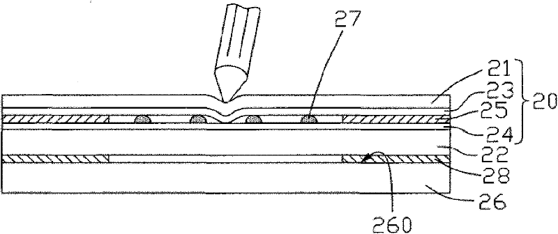
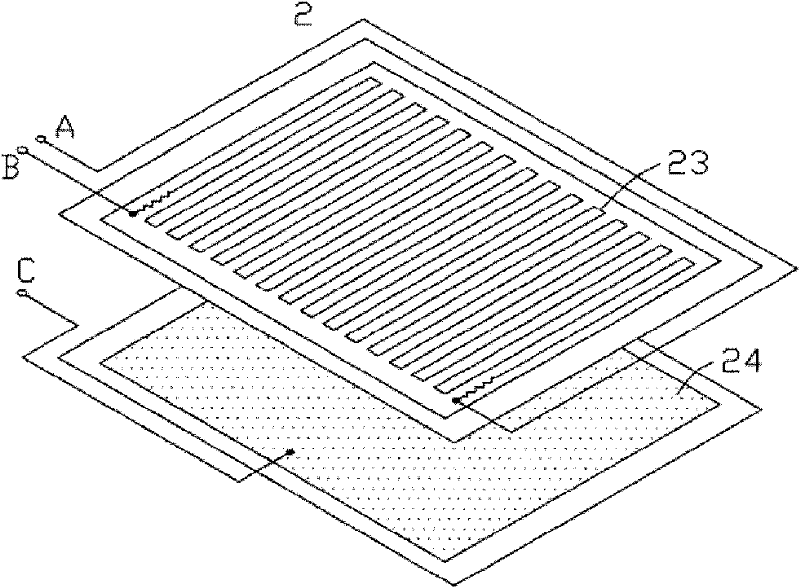
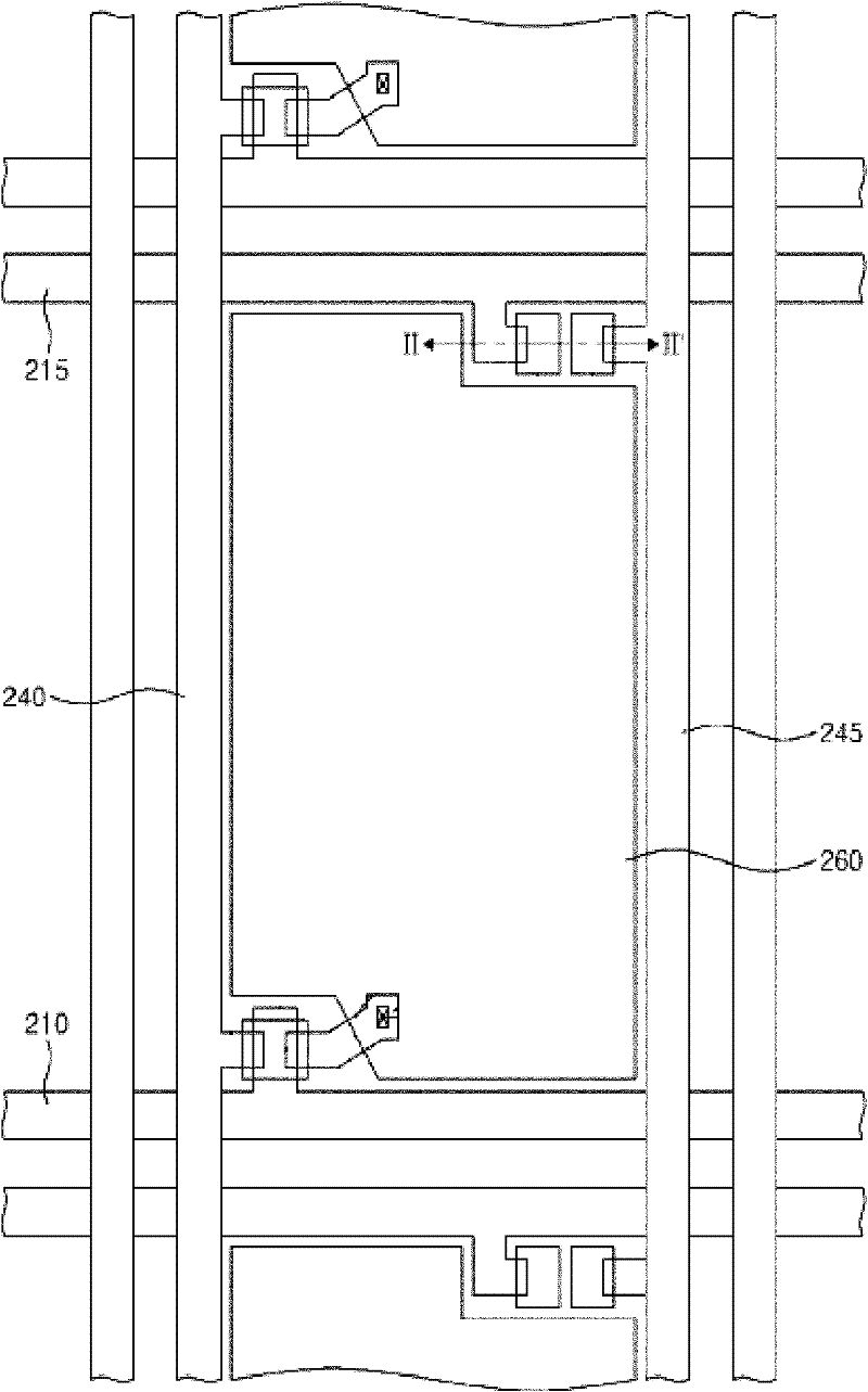
[0042] In order to solve the problems described in the background technology, the present invention provides a touch display device, which includes: an array substrate, a liquid crystal layer, and a color filter substrate in order from bottom to top, and also includes: scanning lines, data lines, TFT Switches and detection lines, wherein the scan lines are connected to the gate of the TFT switch for providing a scan signal for turning on t...


PUM


Abstract

A touch display device includes an array base plate, a color film base plate and a liquid crystal layer, wherein the array base plate includes a plurality of scanning lines and data lines perpendicularly intersected, and a plurality of pixel units limited by the multiple scanning lines and the data lines, and further includes a detecting line arranged in the scanning line direction and a detecting line arranged in the data line direction; the detecting line arranged in the scanning line direction, and the scanning lines are arranged at different layers, are isolated by an insulating layer, and are overlapped in the display direction; a detecting part is arranged at an intersection of the detecting line arranged in the scanning line direction and the detecting line arranged in the data line direction; a touch terminal is arranged at a part on one side of the color film base plate, the part corresponds to the detecting part, and the side of the color film base plate corresponds to the array base plate; the detecting part and the touch terminal are matched; a touch signal is generated under the action of external force; and the display zone area occupied by the detecting lines is reduced, so that the aperture opening ratio is increased.

Description

technical field [0001] The present invention relates to the field of touch display, in particular to an embedded touch display device. Background technique [0002] As an input medium, a touch display device is currently the simplest, most convenient and natural way of human-computer interaction. Therefore, touch display devices are more and more applied to various electronic products, such as mobile phones, notebook computers, MP3 / MP4 and so on. [0003] A resistive touch display device is disclosed in the Chinese patent document with publication number CN101393503A. refer to figure 1 , the resistive touch display device 2 includes a display 26 having a display surface 260 and a touch screen 20 disposed on the display surface 260 . The touch screen 20 is bonded to the side of the display surface 260 of the display 26 through a sealant 28 . The touch screen 20 includes a first substrate 21 and a second substrate 22 oppositely disposed. The first transparent conductive l...

Claims


Application Information

Patent Timeline
Patent Type & Authority Applications(China)
IPC IPC(8): G06F3/041G02F1/133
Inventor 黄贤军
Owner SHANGHAI TIANMA MICRO ELECTRONICS CO LTD
Features
  • Generate Ideas
  • Intellectual Property
  • Life Sciences
  • Materials
  • Tech Scout
  • Unparalleled Data Quality
  • Higher Quality Content
  • 60% Fewer Hallucinations
Learn More