Temperature compensation method in charging process of storage battery

A technology of temperature compensation and charging process, which is applied in the direction of battery circuit devices, current collectors, electric vehicles, etc., can solve the problems of battery charging, reducing charging efficiency, adjusting charging voltage, etc., to achieve the effect of ensuring working efficiency

Inactive Publication Date: 2012-07-04
张家港市华为电子有限公司
5 Cites 5 Cited by

AI-Extracted Technical Summary

Problems solved by technology

At present, the temperature monitoring device and temperature monitoring method used to monitor the temperature change of the battery are too simple, and cannot well realize the purpose of adjusting the charging voltage in t...

Abstract

The invention discloses a temperature compensation method in a charging process of a storage battery, which includes the following steps: presetting a standard temperature range and a normal temperature range in a single chip microcomputer, sampling a first initial temperature of the storage battery and a second initial temperature of a charging circuit unit and respectively storing the two initial temperature values which are eligible after comparison in a storage of the single chip microcomputer. In work, the single chip microcomputer compares real-time temperature of the storage battery with the normal temperature range and the standard temperature and timely increases or decreases charging voltage according to difference between the real-time temperature and the standard temperature. If the real-time temperature exceeds the normal temperature range, the single chip microcomputer adopts the real-time temperature value of a charging circuit unit as the evidence of temperature compensation in charging to finish the charging work. By means of the temperature compensation method, the charging voltage can be timely adjusted according to charging temperature of the storage battery, so that working efficiency of charging can be well guaranteed.

Application Domain

Technology Topic

Image

  • Temperature compensation method in charging process of storage battery
  • Temperature compensation method in charging process of storage battery

Examples

  • Experimental program(1)

Example Embodiment

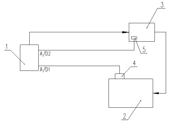
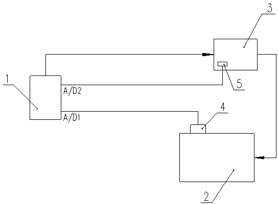
[0010] The present invention will be further described below in conjunction with the drawings and specific embodiments.
[0011] Such as figure 1 The temperature monitoring and compensating device applied to the temperature compensation method of the present invention in the battery charger shown includes: a charging circuit unit 3 and a battery 2, the output of the charging circuit unit 3 is connected to the charging electrode of the battery 2, the The charging circuit unit 3 and the battery 2 are in the same temperature environment, a first temperature sensor 4 is provided on the body of the battery 2, and a second temperature sensor 5 is provided on the charging circuit unit 3, the first temperature sensor 4 and the first temperature sensor 4 The signal output ends of the two temperature sensors 5 are respectively connected with the A/D1 sampling port and the A/D2 sampling port of the single-chip microcomputer 1, and the output control signal of the single-chip microcomputer 1 is connected with the control terminal of the charging circuit unit 3. In this embodiment, the same temperature environment refers to when the charging circuit unit has not yet started charging the battery, or at the initial moment of charging, the environment temperature of the charging circuit unit and the battery is basically the same-two The temperature difference does not exceed 8°C, and there is no separate heat or cold source to heat or cool the charging circuit unit or battery pack separately.
[0012] In actual work, the steps of the temperature compensation method in the battery charging process of the present invention are as follows: (1) Pre-set the standard temperature and the normal temperature range of the battery 2 during the charging in the single chip microcomputer 1. In this embodiment , The standard temperature is 25°C, and the normal temperature range is -40°C to 55°C; (2) At the beginning of the charging circuit unit 3 charging the battery 2, the A/D1 sampling port of the single-chip microcomputer 1 passes The first temperature sensor 4 arranged on the body of the battery 2 detects the temperature of the battery 2, which is recorded as the initial temperature 1. The A/D2 sampling port of the single-chip microcomputer 1 detects the charging circuit unit through the second temperature sensor 5 arranged on the charging circuit unit 3 The temperature of 3 is recorded as initial temperature two, and the two initial temperature values ​​are compared. If the temperature difference between the two is within a reasonable range-not more than 8°C, then the two initial temperature values ​​are stored in the microcontroller 1 In the memory (RAM or EEPROM); if the temperature difference between the two exceeds a reasonable range, adjust the positions of the battery 2 and the charging circuit unit 3 respectively until the temperature difference between the two meets the requirements; (3). The work continues, the A/D1 sampling port of the single-chip microcomputer 1 continuously samples the real-time temperature of the battery 2 through the first temperature sensor 4; compares the sampled real-time temperature with the preset standard temperature and normal temperature range; if When the real-time temperature is lower than the standard temperature, the single-chip microcomputer 1 sends a signal to increase the charging voltage of the charging circuit unit 3 relative to the standard charging voltage; if the real-time temperature is higher than the standard temperature, the single-chip microcomputer 1 sends a signal to make the charging circuit unit 3 lower the charging voltage relative to the standard charging voltage (4). If the real-time temperature exceeds the normal temperature range, it is judged that the first temperature sensor 4 or the A/D1 sampling port is faulty, and the single-chip microcomputer 1 no longer uses the temperature value collected by the A/D1 sampling port as charging The basis of time temperature compensation, MCU 1 will use the temperature value collected by the A/D2 sampling port as the basis of temperature compensation during charging, and complete the charging work according to the compensation method of step (3).
[0013] It can be seen from the above that using the temperature compensation method of the present invention during battery charging can adjust the charging voltage in time according to the real-time temperature of the battery during charging, so as to well ensure the work efficiency during charging.
[0014] The above are only specific application examples of the present invention, and do not constitute any limitation to the protection scope of the present invention. In addition to the foregoing embodiments, the present invention can also have other embodiments. All technical solutions formed by equivalent replacements or equivalent transformations fall within the scope of protection claimed by the present invention.

PUM

no PUM

Description & Claims & Application Information

We can also present the details of the Description, Claims and Application information to help users get a comprehensive understanding of the technical details of the patent, such as background art, summary of invention, brief description of drawings, description of embodiments, and other original content. On the other hand, users can also determine the specific scope of protection of the technology through the list of claims; as well as understand the changes in the life cycle of the technology with the presentation of the patent timeline. Login to view more.

Similar technology patents

Wireless conference system

Owner:方图智能(深圳)科技集团股份有限公司

Classification and recommendation of technical efficacy words

  • Guaranteed work efficiency

Adjustable composite pressure-boosting air intake system

InactiveCN103306805AGuaranteed work efficiencyImproved low-speed torque characteristics and acceleration response characteristicsInternal combustion piston enginesCombustion-air/fuel-air treatmentForced inductionBypass valve
Owner:BEIJING INSTITUTE OF TECHNOLOGYGY

Automatic and efficient gluing device for shoemaking

ActiveCN109123917AThe amount of glue applied is stableGuaranteed work efficiencyShoe gluingPistonEngineering
Owner:泉州卓展商贸有限公司
Why Eureka
Try Eureka