Tangential rotor for rotating motor

A technology for rotating electrical machines and rotors, applied in the field of tangential rotors, which can solve problems such as low utilization of permanent magnets, increase of motor output, and influence on rotor applications, so as to improve the utilization of magnets, reduce production costs, and reduce magnetic flux leakage of magnets Effect

Inactive Publication Date: 2012-07-04
MIDEA WELLING MOTOR TECH SHANGHAI
View PDF3 Cites 10 Cited by
  • Summary
  • Abstract
  • Description
  • Claims
  • Application Information

AI Technical Summary

Problems solved by technology

[0002] In the prior art, the magnetic flux of each pole of the circumferentially magnetized embedded permanent magnet motor is provided by two permanent magnets connected in parallel, which effectively increases the magnetic flux density in the air gap between the stator and the rotor, thereby increasing the output of the motor, such as figure 1 As shown; however, the utilization rate of the permanent magnet at the bottom is low, and the magnetic flux leakage is abundant, and the rotating shaft often requires stainless steel, or uses a magnetically isolated copper sleeve, such as figure 2 As shown, the cost is very high, which affects the application of this structure rotor

Method used


Image

  • Tangential rotor for rotating motor
  • Tangential rotor for rotating motor
  • Tangential rotor for rotating motor

Examples


no. 1 example

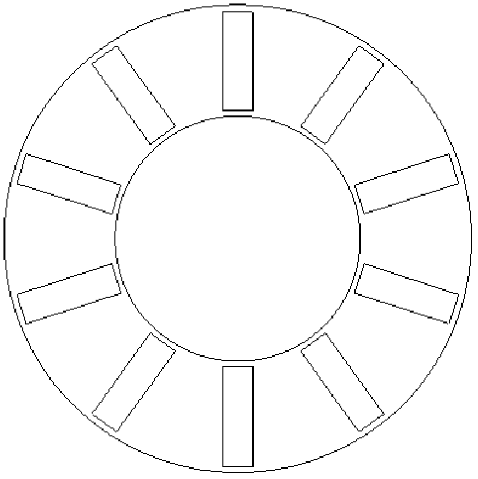
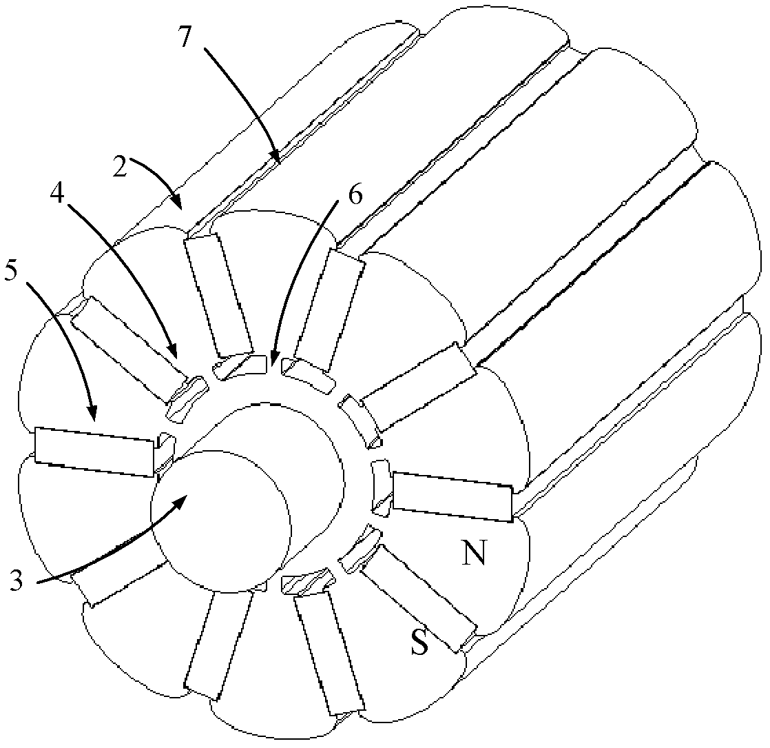
[0014] see image 3 , the tangential rotor of this rotating electrical machine includes a rotor composed of a rotating shaft 3 and a laminated iron core 2, and the laminated iron core 2 is provided with several permanent magnet poles that rotate along the axis of the rotating shaft 3 and are magnetized along the circumferential direction of the rotor relative to the axis 5. The permanent magnet pole part 5 is embedded in the laminated iron core 2 through the permanent magnet slot 4, the side of the permanent magnet slot 4 near the air gap is connected or disconnected from the laminated iron core 2, and the distance between the sides near the rotating shaft is 6 The circumferential width is 0.1-5 mm.

[0015] In this embodiment, the rotor is a 10-pole rotor, and there are 10 permanent magnet poles 5 in total. The side 7 of the permanent magnet slot 4 near the air gap is disconnected from the laminated core 2 , and the polarities of the adjacent permanent magnet poles 5 are oppo...

no. 2 example

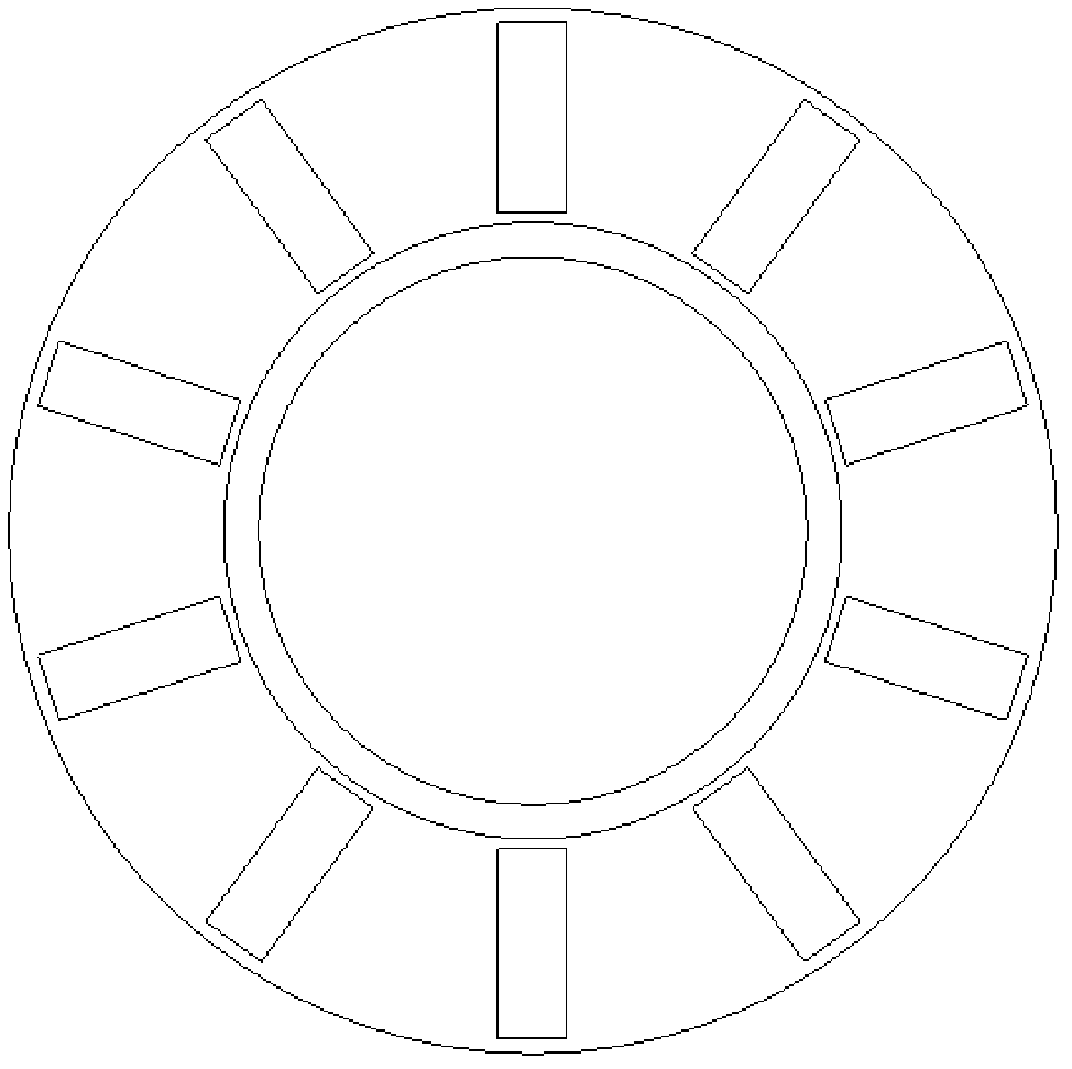
[0017] see Figure 4 The main difference between the tangential rotor of this rotating electrical machine and the first embodiment is that the side 7 of the permanent magnet slot 4 near the air gap is connected to the laminated iron core 2 . Other unmentioned parts are the same as the first embodiment and will not be repeated.


PUM


Abstract

The invention discloses a tangential rotor for a rotating motor. The tangential rotor comprises rotor consisting of a revolving shaft and laminated iron cores, wherein a plurality of permanent magnetic pole parts which rotate along the axis of the revolving shaft and are magnetized along the circumferential direction of the rotor relative to the axis are arranged in the laminated iron cores; the permanent magnetic pole parts are embedded into the laminated iron cores through permanent magnetic grooves; one sides of the permanent magnetic grooves which are close to air gaps are connected with or disconnected from the laminated iron cores; the spacing circumferential widths among one sides of the permanent magnetic grooves which are close to the revolving shaft are 0.1-5 millimeters; the polarities of adjacent permanent magnetic pole parts are reverse; and the spacing circumferential widths among one sides of the permanent magnetic grooves which are close to the revolving shaft are 0.4-3 millimeters. In the tangential rotor, the permanent magnetic grooves for embedding the permanent magnetic pole parts are formed on the laminated iron cores, and the polarities of adjacent permanent magnetic parts are reverse, so that the structure is simple and reasonable, the phenomenon of magnetic leakage of a magnet can be avoided, the utilization ratio of the magnet is increased, the problem that the revolving shaft is made of a stainless steel material or a magnetic insulating copper sleeve is solved, and the manufacturing cost is effectively lowered.

Description

technical field [0001] The invention relates to a rotating electrical machine, in particular to a tangential rotor of the rotating electrical machine. Background technique [0002] In the prior art, the magnetic flux of each pole of the circumferentially magnetized embedded permanent magnet motor is provided by two permanent magnets connected in parallel, which effectively increases the magnetic flux density in the air gap between the stator and the rotor, thereby increasing the output of the motor, such as figure 1 As shown; however, the utilization rate of the permanent magnet at the bottom is low, and the magnetic flux leakage is abundant, and the rotating shaft often requires stainless steel, or uses a magnetically isolated copper sleeve, such as figure 2 As shown, the cost is very high, which affects the application of this structure rotor. Contents of the invention [0003] The object of the present invention is to provide a tangential rotor of a rotating electrica...

Claims


Application Information

Patent Timeline
Patent Type & Authority Applications(China)
IPC IPC(8): H02K1/27
Inventor 葛笑陈金涛诸自强
Owner MIDEA WELLING MOTOR TECH SHANGHAI
Why Eureka
Try Eureka