Magnetic pole structure of permanent magnet synchronous direct-driven motor and design method thereof

A direct-drive motor, permanent magnet synchronous technology, applied in the magnetic circuit shape/style/structure, magnetic circuit rotating parts and other directions, can solve the problems of affecting control accuracy, generating harmonic torque, etc. torque, vibration and noise reduction, long working life

Active Publication Date: 2012-07-04
INST OF ELECTRICAL ENG CHINESE ACAD OF SCI
View PDF4 Cites 17 Cited by
  • Summary
  • Abstract
  • Description
  • Claims
  • Application Information

AI Technical Summary

Problems solved by technology

The no-load air-gap flux density waveform formed by the main pole along the armature surface is close to a flat-top wave. The air-gap flux density includes many harmonic components, especially the 3rd, 5th, and 7th harmonics, which will lead to harmonic torque , affecting the control accuracy

Method used


Image

  • Magnetic pole structure of permanent magnet synchronous direct-driven motor and design method thereof
  • Magnetic pole structure of permanent magnet synchronous direct-driven motor and design method thereof
  • Magnetic pole structure of permanent magnet synchronous direct-driven motor and design method thereof

Examples


Embodiment Construction

[0023] The present invention will be further described below in conjunction with the accompanying drawings and specific embodiments.

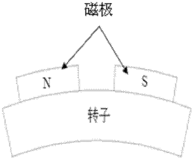
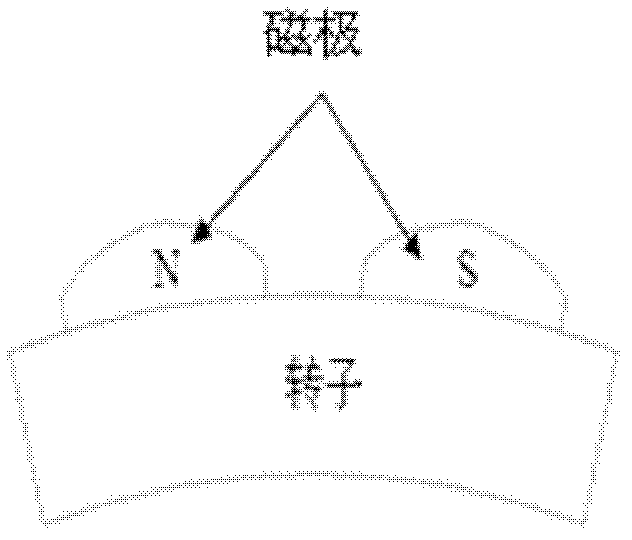
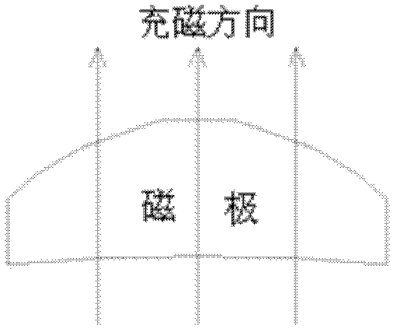
[0024] The magnetic pole structure of the present invention is as Figure 1b As shown, the outer surface of the magnetic pole is composed of multiple slopes with different slopes, the radius of the inner surface of the magnetic pole is the same as the radius of the rotor yoke, the two sides of the magnetic pole are parallel, and the parallel magnetization method is adopted, as shown in Figure 1c shown. Because it is usually not necessary to design a completely sinusoidal flux density waveform, it is only necessary to design an approximate sinusoidal waveform according to the requirements of the harmonic content. In this case, the design of poles with unequal thickness is carried out in the following way.

[0025] The design method of the unequal thickness magnetic pole of the present invention is as figure 2 As shown, first take points a1 ...


PUM


Abstract

The invention relates to a magnetic pole structure of a permanent magnet synchronous direct-driven motor. The magnetic poles are embedded in the circumference of the surface of a rotor in a manner that an N pole and an S pole are alternated, and are opposite to a stator; and a layer of air gap is arranged between the stator and the rotor. The stator comprises an iron core and a winding; and the rotor is of a hollow shaft structure or a solid shaft structure. The magnetic poles of the rotor adopt the magnetic poles with unequal thicknesses, and are uniformly distributed around the surface of the rotor of the motor, so that a no-load magnetic flux density waveform of the air gap is approximate to a sine wave. According to the magnetic pole, a design idea of an inverse problem of an electromagnetic field is adopted, the centers of the magnetic poles with equal thickness are used as a symmetrical axial line, and the thicknesses on two ends of the magnetic poles are gradually reduced, so that an initial scheme of the magnetic poles with unequal thicknesses is obtained. Electromagnetic field software simulation is utilized to obtain the magnetic flux density waveform of the air gap, a fundamental wave and a harmonic component are analyzed, partial size of each magnetic pole is adjusted according to design requirements, and multiple replication is carried out until a design goal is optimized. Due to the adoption of the magnetic pole structure, the vibration and the noise of the permanent magnet synchronous direct-driven motor can be reduced.

Description

technical field [0001] The invention relates to a magnetic pole of a permanent magnet synchronous direct drive motor and a design method thereof. Background technique [0002] The existing surface-mounted poles of permanent magnet synchronous motors often adopt a tile-shaped pole structure of equal thickness. The no-load air-gap flux density waveform formed by the main pole along the armature surface is close to a flat-top wave, and the air-gap flux density includes many harmonics. Wave components, especially the 3rd, 5th, and 7th harmonics, will result in harmonic torque. In addition, because the cogging torque introduced by the slotting of the motor stator is inevitable, a certain cogging and harmonic torque generally exist in the current permanent magnet direct drive motor. Larger torque ripple will increase the control difficulty and stability of the system, especially at low speeds. The traditional method is to eliminate the cogging torque by using the stator chute or...

Claims


Application Information

Patent Timeline
Patent Type & Authority Applications(China)
IPC IPC(8): H02K1/27
Inventor 许海平方程
Owner INST OF ELECTRICAL ENG CHINESE ACAD OF SCI
Why Eureka
Try Eureka