Rotor position detection device for permanent magnet motor

A technology of rotor position detection and permanent magnet motor, applied in electromechanical devices, electrical components, etc., can solve problems such as increased cost, disadvantageous motor structure optimization, increased axial space, etc., and achieves strong induction capability, simple and reasonable structure, and applicable scope. wide effect

Active Publication Date: 2012-07-04
MIDEA WELLING MOTOR TECH SHANGHAI
View PDF7 Cites 12 Cited by
  • Summary
  • Abstract
  • Description
  • Claims
  • Application Information

AI Technical Summary

Problems solved by technology

Today, with the high price of permanent magnets, increasing the amount of permanent magnets to provide position detection signals will undoubtedly increase the cost significantly, and installing or increasing the length of permanent magnets will increase the axial space, which is not conducive to the optimization of the motor structure

Method used


Image

  • Rotor position detection device for permanent magnet motor
  • Rotor position detection device for permanent magnet motor
  • Rotor position detection device for permanent magnet motor

Examples


no. 1 example

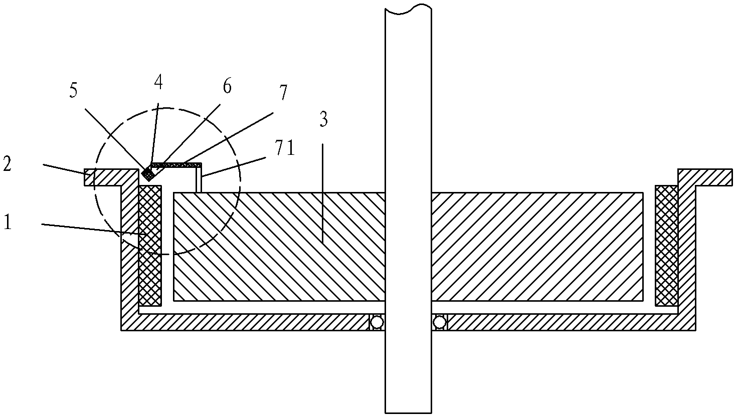
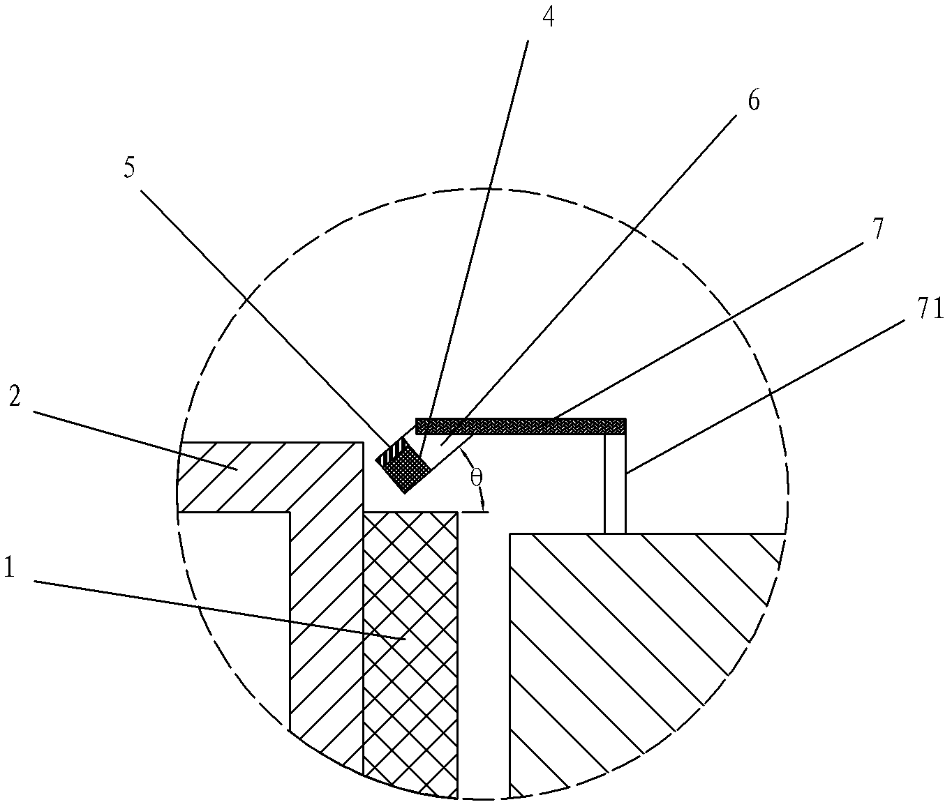
[0029] see Figure 1-Figure 7 , the rotor position detection device of the permanent magnet motor, comprising a Hall position sensor 4 and a permanent magnet 1, a rotor core 2 and a stator core 3 constituting the permanent magnet motor, the permanent magnet 1 is located at the rotor core 2 and the stator core 3 Between the permanent magnet 1 and the rotor core 2, the Hall position sensor 4 is arranged above the upper surface of the permanent magnet 1, and a certain space is reserved between the Hall position sensor 4 and the upper surface of the permanent magnet 1 . The size of this space is determined by the signal strength of the Hall position sensor 4 and the safety distance in actual work.

[0030] In this embodiment, the permanent magnet motor is an outer rotor surface-mounted permanent magnet motor, the stator core 3 is located inside the rotor core 2 , and the permanent magnet 1 is in contact with the inner wall of the rotor core 2 .

[0031] exist Figure 1-Figure 2...

no. 2 example

[0061] see Figure 8-Figure 9 , in this embodiment, the permanent magnet motor is an inner rotor surface mount permanent magnet motor, the rotor core 2 is located inside the stator core 3 , and the permanent magnet 1 is in contact with the outer circumference of the rotor core 2 .

[0062] In fact, the position detection principle of the present invention is mainly aimed at the leakage magnetic field at the end, so there is no obvious distinction for any kind of permanent magnet motor. See the first embodiment for the rest of the undescribed parts, and will not repeat them here.


PUM


Abstract

The invention discloses a rotor position detection device for a permanent magnet motor. The rotor position detection device comprises a Hall position sensor, a permanent magnet, a rotor core and a stator core, wherein the permanent magnet, the rotor core and the stator core form the permanent magnet motor; the permanent magnet is positioned between the rotor core and the stator core, and is connected with the rotor core; the Hall position sensor is arranged above the upper surface of the permanent magnet; a certain space is reserved between the Hall position sensor and the upper surface of the permanent magnet; the axis of the Hall position sensor forms an included angle Theta with the upper surface of the permanent magnet; the detection surface of the Hall position sensor faces the upper surface of the permanent magnet; a magnetization lining plate is arranged on the back surface of the Hall position sensor; the Hall position sensor is connected with a printed circuit board (PCB) through a non-magnetization bracket; the PCB is connected with the stator core through a PCB bracket; and a signal wire and a power cord of the Hall position sensor are electrically connected with a preposed processing circuit on the PCB. The device has the characteristics of simple and rational structure, high sensing capability and wide application range.

Description

technical field [0001] The invention relates to a permanent magnet motor, in particular to a rotor position detection device of the permanent magnet motor. Background technique [0002] Surface-mounted permanent magnet motors have become one of the main drive motors in industrial automation, home appliances, automobiles and other industries due to their low production cost and reliable process. However, whether it is a permanent magnet brushless DC motor or a permanent magnet synchronous motor, it needs a position detection device to provide a rotor position signal for the driver, so the accuracy and reliability of the position detection device become the key to system reliability. [0003] In occasions where cost is not considered or extremely high-precision precision drives are required, photoelectric encoders or resolvers are often used as position detection devices. However, the cost of these two position detection devices is relatively high, sometimes even exceeding the...

Claims


Application Information

Patent Timeline
Patent Type & Authority Applications(China)
IPC IPC(8): H02K29/08
Inventor 吴迪陈金涛诸自强
Owner MIDEA WELLING MOTOR TECH SHANGHAI
Why Eureka
Try Eureka