Eureka AIR delivers breakthrough ideas for toughest innovation challenges, trusted by R&D personnel around the world.

Multi-clock-ring based method for avoiding clock jitter in switching process

A technology of clock switching and master clock, which is applied in multiplexing communication, data exchange network, time division multiplexing system, etc. It can solve the problems of time jitter, inconsistency between master clock A and B, accidents, etc., and achieve improved Reliability and stability, smooth switching process, avoiding the effect of time jitter

Active Publication Date: 2015-01-28
GUANGZHOU PTSWITCH COMP TECH +1
View PDF2 Cites 0 Cited by
  • Summary
  • Abstract
  • Description
  • Claims
  • Application Information

AI Technical Summary

Problems solved by technology

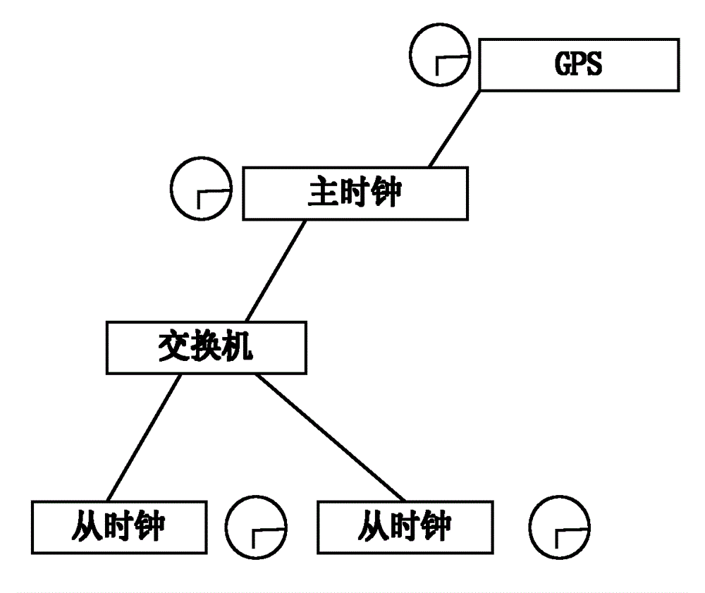
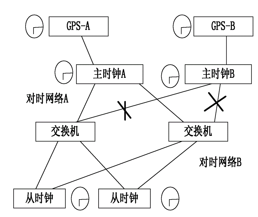
[0005] This method has such a problem that the two clocks are respectively connected to different GPS signals of the Global Positioning System. Since the GPS signals A and B of the Global Positioning System cannot be completely synchronized, the master clocks A and B It is inconsistent. Once A fails and B starts to work, the time of the entire network needs to jump from A to B. There will be time jitter during the jump, and the jump needs a convergence time. During this time, it will Affect the correct time synchronization of network equipment, resulting in accidents, which will undoubtedly affect the stability of the entire synchronization system

Method used


Image

  • Multi-clock-ring based method for avoiding clock jitter in switching process
  • Multi-clock-ring based method for avoiding clock jitter in switching process
  • Multi-clock-ring based method for avoiding clock jitter in switching process

Examples


Embodiment

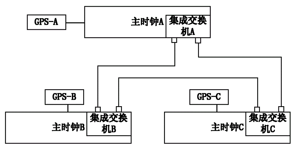
[0026] In this embodiment, three main clocks are used to form a clock ring as an example to describe the following.

[0027] The connection diagram of the multi-clock ring composed of three main clocks is as follows: image 3 As shown, a ring network structure is formed among master clock A, master clock B and master clock C, and each master clock is provided with a micro-switch for sending and receiving calibration time messages. The method for preventing clock switching jitter based on multiple clock rings of the present invention comprises the following steps:

[0028] In the first step, a ring network structure is formed among master clock A, master clock B and master clock C;

[0029] In the second step, the three master clocks (master clock A, master clock B, and master clock C) all start the topology discovery protocol (using rapid spanning tree protocol) on the ring network port to discover the ring network situation and finally determine one of them. Lines are disco...


PUM


Abstract

The invention provides a multi-clock-ring based method for avoiding clock jitter in the switching process. The method comprises the following steps: the first step, the main clocks are connected with each other to form a ring network structure in a ring-shaped way; the second step, each main clock initiates a topology discovery protocol at an interface of the ring network to discover the ring network situation and determine one of lines for being used as a backup line; the third step: all main clocks on the ring network initiates an IEEE (institute of electrical and electronic engineers) 1558 protocol at the network interface and uses a BMC (best master clock) algorithm to determine which main clock can finally be the highest main clock; then the ring network interfaces of other main clocks are changed into slave clock nodes and the other main clocks stop calibrating the self GPS (global positioning system) time to the 1588 clock, in turn, the other main clocks conduct the calibration according to the clock of the highest main clock by the 1588 protocol and simultaneously produce a warning event. The method provided by the invention can avoid the time jitter occurred in the switching process of the main clock.

Description

technical field [0001] The invention relates to the technical field of synchronous time synchronization, and more specifically, relates to a method for preventing clock switching jitter by using multiple clock loops. Background technique [0002] The IEEE 1588 Precision Clock Synchronization Protocol enables precise synchronization of clocks in measurement and control systems used to implement network communications, local computing and distributed objects. The communication between clocks is carried out through a communication network, and the protocol establishes a master-slave relationship between clocks in the system. All clocks ultimately derive their own time from the master clock's time. Among them, IEEE 1588 has three types of equipment, namely: ordinary clock, boundary clock and transparent clock. Ordinary clocks can be divided into master clocks and slave clocks according to their roles, and only contain one Precision Time Protocol (PTP) port; the boundary clock ...

Claims


Application Information

Patent Timeline
Patent Type & Authority Patents(China)
IPC IPC(8): H04J3/06H04L12/24
Inventor 竹之涵蔡泽祥黄毅刘文泽苏忠阳
Owner GUANGZHOU PTSWITCH COMP TECH
Why Eureka
Eureka Blog
Learn More